
Automatic eyesight testing device

An automatic test device and vision technology, which is applied in eye test equipment, medical science, diagnosis, etc., can solve the problems of low technical content, waste of labor costs, inaccurate vision detection, etc., and achieve the effect of convenient operation and accurate results

Pending Publication Date: 2019-03-22
NANNING COLLEGE FOR VOCATIONAL TECH
View PDF9 Cites 0 Cited by
  • Summary
  • Abstract
  • Description
  • Claims
  • Application Information

AI Technical Summary

Problems solved by technology

[0004] The above-mentioned vision testing method is a traditional manual vision test, which requires special personnel to do special work, but this work has low technical content, wastes labor costs, and also results in inaccurate vision testing.

Method used


Image

  • Automatic eyesight testing device
  • Automatic eyesight testing device

Examples


Embodiment Construction

[0017] In order to understand the above-mentioned purpose, features and advantages of the present invention more clearly, the technical solutions of the present invention will be described in further non-limiting detail below in conjunction with the accompanying drawings and specific embodiments.

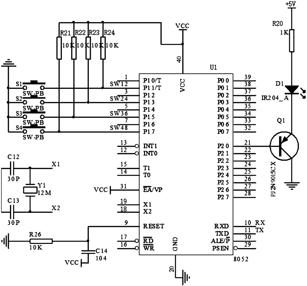
[0018] See figure 1 , The test transmitter includes a first single-chip microcomputer U1, a first button S1, a second button S2, a third button S3, a fourth button S4 and an infrared emitting circuit. The first single-chip microcomputer U1 is an 8052-type single-chip microcomputer, and its periphery is provided with a crystal oscillator circuit. The crystal oscillator circuit includes a capacitor C12, a capacitor C13, and a crystal oscillator Y1. The frequency of the crystal oscillator Y1 is 12M. The first button S1, the second button S2, the third button S3 and the fourth button S4 are connected in parallel with each other, and are respectively coupled with P1.1, P1.3, P1.5, and P1...


PUM

PropertyMeasurementUnit
Crystal frequencyaaaaaaaaaa

Abstract

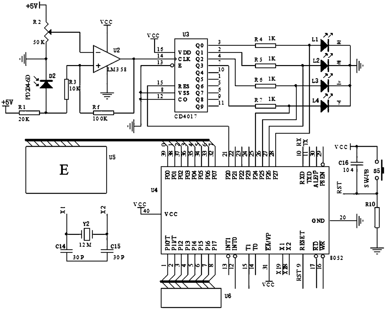
The invention discloses an automatic eyesight testing device, which comprises a testing emitter and a testing receiver. The testing emitter comprises a first single-chip microcomputer, a first key, asecond key, a third key, a fourth key and an infrared emission circuit. The testing receiver comprises an infrared receiving circuit, a comparator, a counter, a second single-chip microcomputer, a first indicator light, a second indicator light, a third indicator light, a fourth indicator light, a character display screen and a result display screen. The automatic eyesight testing device has advantages that by an infrared wireless signal transmitting technique and a single-chip microcomputer control technique, a person taking eyesight test can complete the eyesight test independently, convenience and quickness in operation and result accuracy are realized, and results can be displayed on a display screen.

Description

technical field [0001] Embodiments of the present invention relate to a vision testing device, in particular, to an automatic vision testing device. Background technique [0002] Visual acuity is generally divided into two categories: distance vision and near vision. The distance vision mostly adopts the international standard eye chart. This table is composed of 12 rows of "E" characters with different sizes and opening directions. The measurement ranges from 0.1-1.5 (or from 4.0 -5.2), each line has a label. [0003] The test method is that the subject's line of sight should be parallel to the line of 1.0, and the distance from the vision chart should be 5 meters. The distance between the vision chart and the subject must be fixed correctly, and the patient should be 5 meters away from the chart. If the indoor distance is less than 5 meters long, a plane mirror should be placed at 2.5 meters to reflect the eye chart. Cover one eye for detection, and identify the directio...

Claims


Application Information

Patent Timeline
IPC IPC(8): A61B3/032
CPCA61B3/0025A61B3/032
Inventor 张叶茂刘红艳艾妮陈新菡
Owner NANNING COLLEGE FOR VOCATIONAL TECH
Learn More