
Rapid gas chromatograph cooling device

A technology of gas chromatograph and cooling device, which is applied in the field of rapid cooling device of gas chromatograph, which can solve the problems of consuming analysis sample time, reducing work efficiency, prolonging cooling time, etc., and achieves faster wind speed, higher cooling efficiency, and faster air flow Effect

Inactive Publication Date: 2019-03-19
山东金普分析仪器有限公司
View PDF0 Cites 2 Cited by
  • Summary
  • Abstract
  • Description
  • Claims
  • Application Information

AI Technical Summary

Problems solved by technology

[0003] In the gas chromatograph, during the working process, the air in the box and the air outside the box are circulated by controlling the switch of the rear door to achieve cooling, but because the exhaust port is adjacent to the air inlet, the hot air discharged from the upper exhaust port has Part of it enters the column box through the air inlet below, resulting in less effective cold air, prolonging the cooling time, greatly consuming the time for staff to analyze samples, and seriously reducing work efficiency

Method used


Image

  • Rapid gas chromatograph cooling device
  • Rapid gas chromatograph cooling device

Examples


Embodiment 1

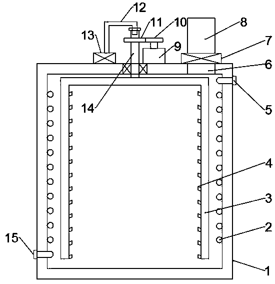
[0019] see figure 1 , in an embodiment of the present invention, a gas chromatograph rapid cooling device includes a column box 1, a motor 9, an exhaust fan 7 and a suction fan 13, the top side of the column box 1 is provided with an air outlet 6, and the air outlet 6 is installed with Exhaust fan 7, exhaust pipe 8 is installed on the exhaust fan 7 through screws, the inner wall of the column box 1 has a cooling water pipe 2 through a mounting ring and screws, the cooling water pipe 2 is spiral, and one end of the cooling water pipe 2 is provided with a cooling water inlet 15 The other end of the cooling water pipe 2 is provided with a cooling water outlet 5, and a hollow shaft 14 is pierced in the middle of the top of the column box 1. The hollow shaft 14 is rotatably connected with the top of the column box 1 through a bearing, and the bottom of the hollow shaft 14 is welded and fixed with an inverted U shape. Shaft 3, both sides of the inverted U-shaped shaft 3 are close to...

Embodiment 2

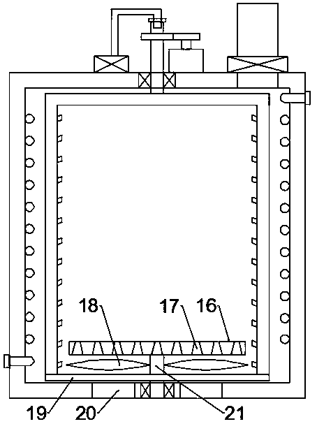
[0021] see figure 2 The difference between this embodiment and Embodiment 1 is that the bottom of the column box 1 is equipped with a rotating shaft 21 through bearings, and the bottom of the column box 1 is provided with air inlets 20 on both sides of the rotating shaft 21, and the air inlets 20 are installed with screws. Dust-proof net, the bottom end of the inverted U-shaped shaft 3 is welded and fixed with the rotating shaft 21 through the fixing rod 19, the top of the rotating shaft 21 is equipped with a disc 16, and a plurality of through holes 17 are evenly opened on the disc 16, and the through holes 17 have a small opening at the top The opening is large, and fan blades 18 are installed on the rotating shaft 21 below the disc 16. When the inverted U-shaped shaft 3 rotates, the fixed plate 19 drives the rotating shaft 21 to rotate, and the rotating shaft 21 drives the fan blades 18 and the disc 16 to rotate. The aperture of the hole 17 makes the wind speed of the fan ...


PUM


Abstract

The invention discloses a rapid gas chromatograph cooling device and relates to the technical field of gas chromatograph cooling. In order to solve the problem that the conventional device is long incooling time, the rapid gas chromatograph cooling device comprises a column box, a motor, an exhaust fan and a suction ventilator, wherein a hollow shaft penetrates through the middle of the top of the column box; an inverted U-shaped shaft is fixedly welded at the bottom of the hollow shaft; the motor is arranged at a position, which is positioned on one side of the hollow shaft, of the top of the column box by virtue of screws; a first gear is arranged at the end of the output shaft of the motor; a second gear is arranged on the top of the hollow shaft; the first gear is meshed with the second gear; a disc is arranged on the top of the rotating shaft; a plurality of through holes are uniformly formed in the disc; and fan blades are arranged at positions, which are positioned below the disc, of the rotating shaft. According to the arrangement of the motor, the first gear, the second gear, the hollow shaft, the inverted U-shaped shaft and the suction ventilator, the hollow shaft drivesthe inverted U-shaped shaft to rotate, so that the interior of the column box can be fully subjected to heat dissipation and cooling. Due to the arrangement of the rotating shaft, the disc and the fan blades, cyclone is formed, the heat is accelerated to take away, and the cooling efficiency is further improved.

Description

technical field [0001] The invention relates to the technical field of gas chromatograph cooling, in particular to a gas chromatograph rapid cooling device. Background technique [0002] Gas chromatography is widely used in fire investigation, petroleum, chemical industry, biochemistry, medicine and health, food industry, environmental protection and so on. In addition to quantitative and qualitative analysis, it can also determine the physical and chemical constants such as distribution coefficient, activity coefficient, molecular weight and Ruisheng specific surface area of ​​the sample on the stationary phase. A gas chromatograph is an instrument for analyzing and detecting the components in the mixed gas. After the analysis sample is vaporized in the inlet, it is carried into the chromatographic column by the carrier gas, and the components in the mixture to be detected have different retention properties. The chromatographic column separates each component, and then in...

Claims


Application Information

Patent Timeline
IPC IPC(8): G01N30/30G01N30/60
CPCG01N30/30G01N30/606
Inventor 侯宗胜何荣文王绍武黄威超王睿
Owner 山东金普分析仪器有限公司
Learn More