
Full focus imaging beam calibration method

A calibration method and an all-focus technology, which can be used in the processing of detection response signals, the use of sound waves/ultrasonic waves/infrasonic waves to analyze solids, and the use of sound waves/ultrasonic waves/infrasonic waves for material analysis. To achieve the effect of improving image energy uniformity, reducing defect quantitative detection error and detection missed rate

Active Publication Date: 2019-03-19
AVIC BEIJING INST OF AERONAUTICAL MATERIALS
View PDF2 Cites 13 Cited by
  • Summary
  • Abstract
  • Description
  • Claims
  • Application Information

AI Technical Summary

Problems solved by technology

However, the acoustic beam calibration of the above-mentioned omni-focus imaging all adopts the theoretical calculation method. In the theoretical formula, only the acoustic wave frequency, the sound velocity of the longitudinal / transverse wave and the material density are considered, but the factors that actually affect the attenuation of the acoustic wave energy are far more than these, and the actual detection There is also a certain difference between the actual parameter values ​​of the ultrasonic array probe and the material to be tested and the theoretical calculation value, which leads to the large quantitative detection error of the sound beam calibration method proposed in the above paper, which is not suitable for the quantitative evaluation of actual ultrasonic testing.

Method used


Image

  • Full focus imaging beam calibration method
  • Full focus imaging beam calibration method
  • Full focus imaging beam calibration method

Examples


Embodiment Construction

[0039] The technical scheme of the present invention will be described in further detail below in conjunction with the accompanying drawings and embodiments:

[0040] The implementation steps of the sound beam calibration method for full focus imaging described in the technical solution of the present invention are as follows:

[0041] Step 1. Make a standard test block

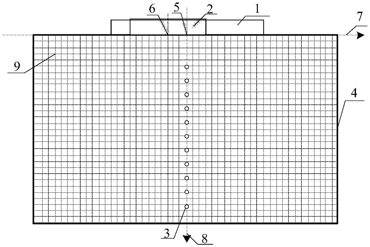
[0042] see attached figure 1 As shown, the standard test block 4 is made of a 304 stainless steel metal test block with a rectangular shape. The standard test block is 94mm long, 25mm wide and 40mm high. 10 transverse holes 3 are machined at equal intervals at the bottom, the diameter of the transverse holes 3 is 1mm, the center of the uppermost transverse hole is 10mm from the upper surface of the standard test block, and the center of the lowermost transverse hole is 10mm away from the lower surface of the standard test block. 3mm, the center distance between adjacent transverse holes 3 is 3mm, the number...


PUM


Abstract

The invention discloses a full focus imaging beam calibration method. According to the method, a beam calibration matrix is established by amplitude information of a horizontal through hole in an actual measured standard test block so as to compensate acoustic energy attenuation. The calibration method comprises the following steps: making a standard test block; acquiring and storing full matrix data; extracting full matrix sub-data; performing full focus imaging on each full matrix sub-data; extracting the amplitude information of the horizontal through hole and generating original calibration data; performing linear interpolation calculation on the original calibration data to generate the beam calibration matrix; and performing beam calibration on full focus imaging. According to the method disclosed by the invention, the quantitative defect detection errors and the missing detection rate can be effectively reduced, and the full focus imaging energy uniformity is improved.

Description

technical field [0001] The invention relates to a sound beam calibration method for full focus imaging, which belongs to the field of non-destructive testing. Background technique [0002] Phased array ultrasonic testing technology is a mature ultrasonic testing method based on ultrasonic array probes. This technology realizes the focusing and deflection of the sound beam by controlling the excitation time of each array element in the ultrasonic array probe, so as to obtain better imaging results. . With the continuous popularization of phased array ultrasonic testing technology, the research of various advanced post-processing imaging algorithms has attracted more and more attention. [0003] The all-focus imaging algorithm is an emerging ultrasonic post-processing imaging technology in recent years. This technology first makes each array element in the ultrasonic array probe emit ultrasonic waves in turn, and all the array element elements independently receive ultrasonic...

Claims


Application Information

Patent Timeline
IPC IPC(8): G01N29/06G01N29/30G01N29/44
CPCG01N29/069G01N29/30G01N29/44
Inventor 徐娜许路路王东升梁菁何方成
Owner AVIC BEIJING INST OF AERONAUTICAL MATERIALS
Learn More