
Device for measuring metal linear expansion coefficient based on pinhole imaging

A small hole imaging and metal wire technology, which is applied in the field of laser measurement, can solve the problems of complex optical path adjustment, low measurement accuracy, and low magnification, and achieve the effects of low optical path adjustment requirements, accurate measurement results, and safe and convenient use

Pending Publication Date: 2019-03-19
SHENYANG INST OF ENG
View PDF53 Cites 1 Cited by
  • Summary
  • Abstract
  • Description
  • Claims
  • Application Information

AI Technical Summary

Problems solved by technology

[0004] The invention provides a device for measuring the linear expansion coefficient of metal based on pinhole imaging, which can effectively solve the problems of low magnification, generally only more than 20 times, low measurement accuracy, complicated optical path adjustment, and long operation time proposed in the background technology.

Method used


Image

  • Device for measuring metal linear expansion coefficient based on pinhole imaging
  • Device for measuring metal linear expansion coefficient based on pinhole imaging
  • Device for measuring metal linear expansion coefficient based on pinhole imaging

Examples


Embodiment

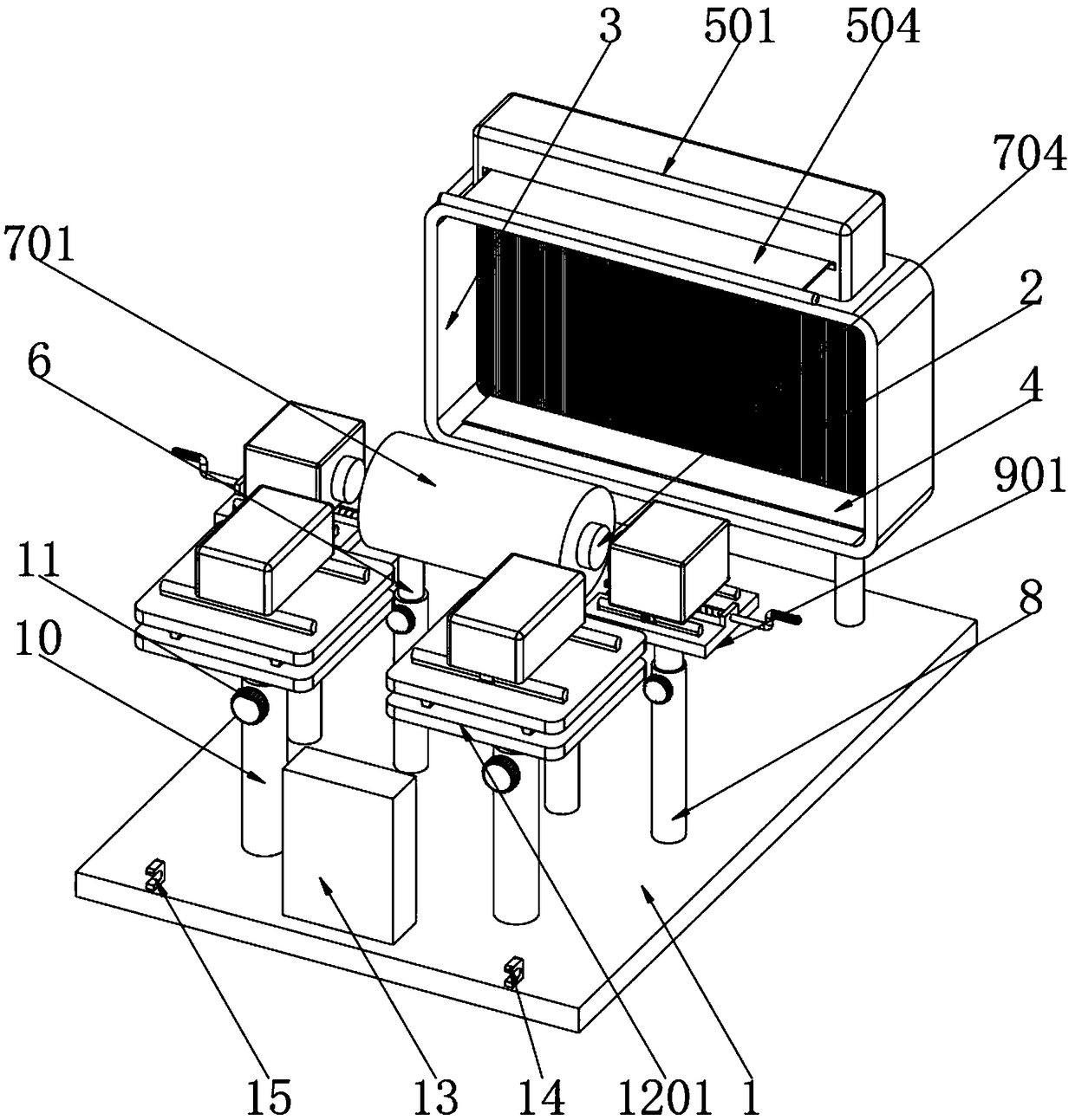
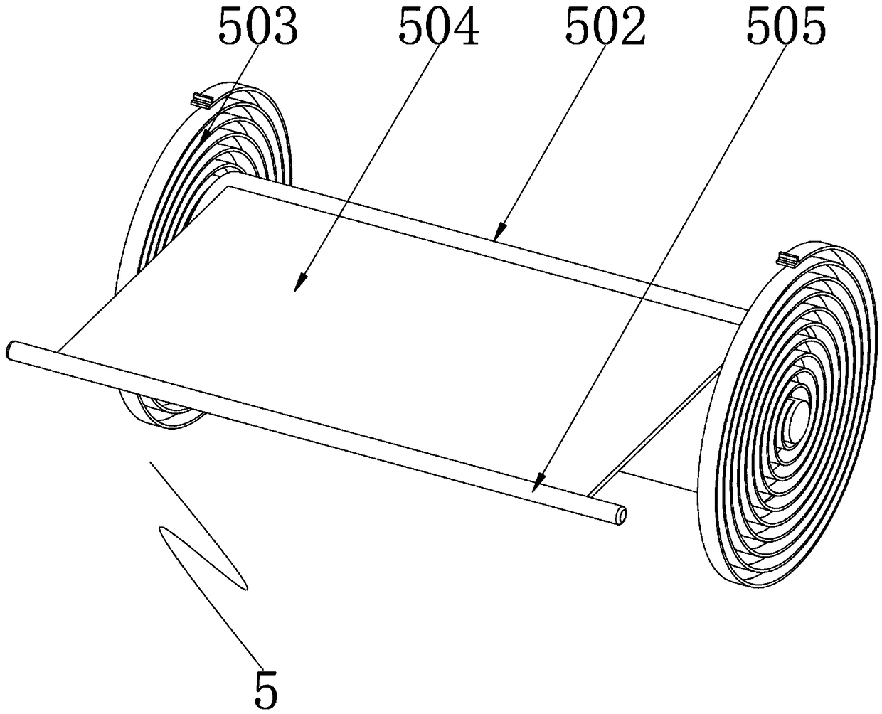
[0043] Example: such as Figure 1-7 As shown, the present invention provides a technical solution, a device for measuring the linear expansion coefficient of metal based on small hole imaging, including a base plate 1, one end of the base plate 1 is welded with a light screen 2 through a support rod, and one side of the light screen 2 is installed by welding There is a cover 3. In order to facilitate direct reading of data, one side of the light screen 2 is pasted with alternate light and dark stripes, and the distance between the stripes is 0.1 mm. In order to absorb the external light, the light on the surface of the light screen 2 More clearly, the inner wall of the shielding cover 3 is coated with black paint, and the inner bottom of the shielding cover 3 is pasted with a black recording board 4;

[0044] A dust-proof assembly 5 is installed on the top of the light screen 2, and the dust-proof assembly 5 includes a storage box 501, a take-up roller 502, a plane scroll spri...

Embodiment 2

[0053] Embodiment 2: The measurement method of the device for measuring the linear expansion coefficient of metal based on pinhole imaging, comprising the following steps:

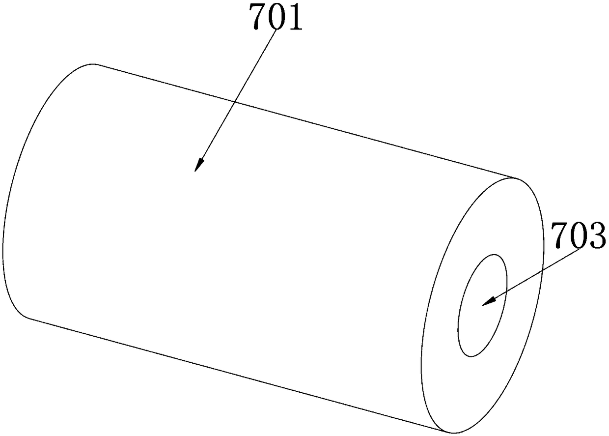
[0054] (1) Measure the original length L of the metal rod 704 0 Finally, the metal rod 704 is inserted into the slot 703, and the positions and heights of the x-axis displacement block 905 and the laser emitter 1208 at both ends of the metal rod 704 are adjusted so that the light energy of the laser emitter 1208 passes through the x-axis displacement block 905 and the laser emitter 1208. The gap formed by one end of the metal rod 704 hits the light screen 2 to form a beam of light;

[0055] (2) Move the x-axis displacement block 905 of the miniature x-axis displacement assembly 9, and record the moving length ΔL, record the light column length variation ΔS on the black recording board 4 below the light screen 2 and record the data, repeat the operation several times and Record multiple sets of data;

[0...


PUM

PropertyMeasurementUnit
distanceaaaaaaaaaa

Abstract

The invention discloses a device for measuring a metal linear expansion coefficient based on pinhole imaging, comprising a bottom plate, wherein one end of the bottom plate is provided with an opticalscreen by welding by a support rod, a shielding cover is arranged at a side edge of the optical screen, alternate light and dark stripes are adhered to one side of the optical screen, the distance between the stripes is 0.1mm, and a black recording plate is adhered to the bottom end at the inner side of the shielding cover. The device is scientific and reasonable in structure and safe and convenient to use, and mini-elongation of two ends of a metal bar can be respectively measured by minitype X-axis displacement components at two ends of the metal bar, so that the measurement result is moreaccurate; the experiment is low in optical path adjusting requirement, only the positions of two laser emitters need to be adjusted, the operation is simple, alternate light and dark stripes with thespacing of 0.1mm are adhered to the surface of the optical screen, direct reading is facilitated, an aluminum alloy pipe with good heat conducting property is adopted as the metal bar for transferringheat for the heating device, and a heating pipe is directly put into the aluminum alloy pipe, so as to avoid heat waste and be more energy-saving and environment-friendly.

Description

technical field [0001] The invention relates to the technical field of laser measurement, in particular to a device for measuring the linear expansion coefficient of metal based on pinhole imaging. Background technique [0002] The expansion coefficient is a physical quantity that characterizes the thermal expansion properties of an object, that is, a physical quantity that characterizes the increase in length, area and volume of an object when it is heated. The increase in length is called "linear expansion", the increase in area is called "surface expansion", and the increase in volume is called " Body expansion”, collectively referred to as thermal expansion, the existing laboratory method of measuring metal linear expansion coefficient is based on the principle of optical levers, and there are the following problems: low magnification, generally only 20 times, measurement accuracy is not high, optical path adjustment Complicated and takes a long time to operate. [0003...

Claims


Application Information

Patent Timeline
Patent Type & Authority Applications(China)
IPC IPC(8): G01N21/84G01N25/16
CPCG01N21/84G01N25/16
Inventor 王秀平应杨江纪彦伟李岩杨楮涵李光耀王一名罗世超张君宇
Owner SHENYANG INST OF ENG
Learn More