Transparent soil model testing apparatus for simulating tunnel excavation and testing method
A transparent soil and transparent technology, applied in measuring devices, using stable tension/pressure to test the strength of materials, instruments, etc., can solve the problems of infeasibility, inability to accurately control the moving distance, etc., to save test time, Reliable results and simple operation
Inactive Publication Date: 2019-03-19
TIANJIN UNIV
View PDF6 Cites 8 Cited by
- Summary
- Abstract
- Description
- Claims
- Application Information
AI Technical Summary
Problems solved by technology
However, when moving the laser, since the moving distance cannot be accurately controlled, and the laser beam may pose a threat to the safety of the experimenters during the moving of the laser, the position of the laser ne
Method used
View moreImage
Smart ImageViewing Examples
Examples
 PUM
 Abstract
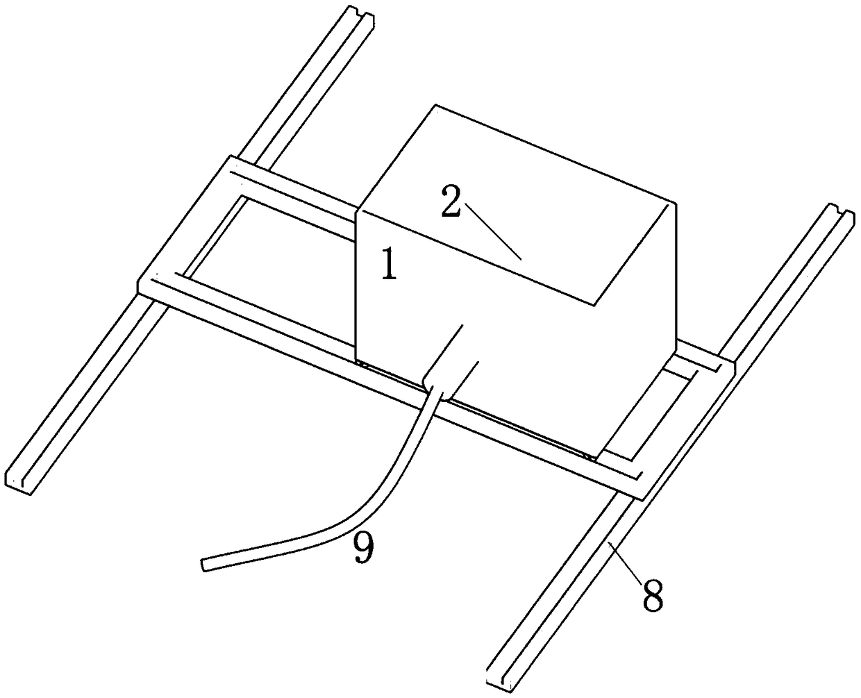
The invention relates to a transparent soil model testing apparatus for simulating tunnel excavation and a testing method. The device comprises a transparent model box, a rigid pipeline, a rubber membrane, a laser transmitter, a camera, an optical platform, a linear guide rail, a pressure controller and a computer, wherein the transparent model box is used for containing transparent soil; and oneend of the rigid pipeline penetrates into the transparent model box. The testing method comprises the following steps: opening a valve to inject water into the rigid pipeline, regulating the pressurecontroller to reach a design pressure, and controlling the pressure to maintain invariable; performing stepwise decompression, simulating the tunnel excavation process, irradiating the transparent soil by the laser transmitter after decompression stabilization, and shooting the continuous patterns by the camera after forming stable patterns; controlling the model box to move by a certain distanceon the linear guide rail, continuously shooting, and forming a spatial deformation pattern parallel to the laser irradiation plane; and processing the mutually parallel patterns so as to obtain a space displacement vector diagram of the laser patterns, and calculating to obtain the space strain diagram. According to the testing apparatus and testing method disclosed by the invention, the deformation field on any section of the tunnel can be continuously and efficiently measured in a non-contact manner.
Description
technical field [0001] The invention relates to a transparent soil model test device and a test method for simulating tunnel excavation, which are mainly suitable for tunnel excavation test simulation in clay and sandy soil layers, and belong to the indoor tunnel excavation model test technology of geotechnical engineering. Background technique [0002] Tunnel construction will cause engineering problems such as deformation of the surrounding soil, ground subsidence or uplift, and instability of the excavation surface. The model test uses a physical model entity, which is equivalent to the similarity principle, boundary conditions and initial conditions under laboratory conditions. The tunnel excavation process is simulated in the model tank or model box, and the tunnel is measured by embedded pressure sensors and displacement gauges. Excavate the deformation and pressure changes of the soil within the influence range, and analyze the deformation, strength and stability char...
Claims
Login to View More Application Information
Patent Timeline
 IPC IPC(8): G01N3/10G01N3/06
CPCG01N3/068G01N3/10G01N2203/0019G01N2203/0048G01N2203/0647G01N2203/0682
Inventor 雷华阳刘敏翟塞北刘英男屠慈科
Owner TIANJIN UNIV
- R&D Engineer
- R&D Manager
- IP Professional
- Industry Leading Data Capabilities
- Powerful AI technology
- Patent DNA Extraction
Learn More Browse by: Latest US Patents, China's latest patents, Technical Efficacy Thesaurus, Application Domain, Technology Topic, Popular Technical Reports.
© 2024 PatSnap. All rights reserved.Legal|Privacy policy|Modern Slavery Act Transparency Statement|Sitemap|About US| Contact US: help@patsnap.com


