A cylinder head assembly and compressor

A cylinder head and component technology, applied in the field of compressors, can solve the problems of high cost of compressors, offset center of gravity of compressors, lengthening of cylinder seat plate distance, etc., to reduce vibration noise, prevent rotational movement, and save overall size Effect

Active Publication Date: 2020-09-22
WANBAO GROUP COMPRESSOR CO LTD
View PDF5 Cites 0 Cited by
  • Summary
  • Abstract
  • Description
  • Claims
  • Application Information

AI Technical Summary

Problems solved by technology

[0004] 1. The cylinder head is designed in a square shape, which occupies a large space inside the compressor shell, which is not conducive to the miniaturization of the compressor;
[0005] 2. The entire cylinder head is large in size and weight, the center of gravity of the compressor is seriously offset, the compressor has large vibration and high noise;
[0006] 3. The weight of the consumed materials is also high, resulting in high cost of the compressor;
[0007] 4. The cylinder head is made of aluminum alloy, which is easy to deform, so it needs a particularly large thickness to ensure sufficient strength, resulting in high cost of the cylinder head; due to the large thickness of the cylinder head, the gap between the movement and the shell is too small, so the shell The body size cannot be further reduced, or the distance between the cylinder seat plate surface cannot be further lengthened;

Method used


Image

  • A cylinder head assembly and compressor
  • A cylinder head assembly and compressor
  • A cylinder head assembly and compressor

Examples


Embodiment Construction

[0029] This section will describe the specific embodiments of the present invention in detail. The preferred embodiments of the present invention are shown in the drawings. The function of the drawings is to supplement the description of the text part of the manual with graphics, so that people can intuitively and vividly understand the text. Each technical feature and overall technical solution of the invention cannot be understood as a limitation on the protection scope of the present invention.

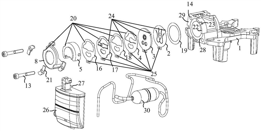
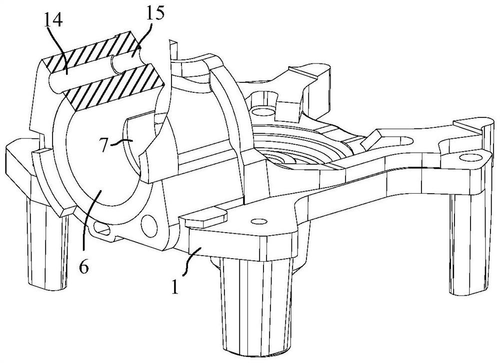
[0030] In the present invention, if there are directions (up, down, left, right, front and back) described, it is figure 1 or Figure 7 The structure shown is for reference description, but it is only for the convenience of describing the technical solution of the present invention, rather than indicating or implying that the technical feature referred to must have a specific orientation, be constructed and operated in a specific orientation, and therefore cannot be understood as a ref...


PUM


Abstract

The invention discloses a cylinder end assembly and a compressor. The cylinder end assembly and the compressor are used in the field of compressors. The cylinder end assembly comprises a cylinder seatand a cylinder end component. The cylinder end component comprises an air suction valve plate, a valve plate, an exhaust valve plate and a cylinder head. The cylinder end component is circular. A cylinder hole is formed in the cylinder seat. The cylinder end component is installed at the front end of the cylinder hole of the cylinder seat through fasteners. A radial positioning fence is arrangedon the cylinder seat. A rotary limiting groove is formed in the radial positioning fence. The air suction valve plate, the valve plate and the exhaust valve plate are all provided with rotary limitingprotrusions matched with the rotary limiting groove. The compressor comprises the cylinder end assembly. The cylinder end component adopts a circular design, and the cylinder end component is installed on the cylinder seat through the fasteners, so that the overall size of the cylinder end component is saved, the material is saved, the weight is reduced, the cost is reduced, and the vibration noise generated when the compressor works is reduced; and meanwhile, the cylinder end component adopts the circular design, and the rotary limiting groove is matched with the rotary limiting protrusionsof the cylinder end component, so that the cylinder end component is prevented from rotationally moving, and the function of accurate positioning is played.

Description

Technical field [0001] The invention is used in the field of compressors, and particularly relates to a cylinder head assembly and a compressor. Background technique [0002] The cylinder head components of the existing compressors include: cylinder head, cylinder head gasket, suction muffler, valve plate parts, suction valve plate, valve plate gasket, cylinder head screws, etc. The number of cylinder head screws is four. Pieces. The cylinder head, cylinder head gasket, valve plate parts, suction valve disc, and valve plate gasket are square in appearance, and cylinder head screw mounting holes are provided at four corners. Correspondingly, a threaded hole is provided on the cylinder seat plate surface (close to the top of the cylinder hole), and four cylinder head screws are matched with the threaded hole to fasten the cylinder head component. [0003] The existing technology has the following shortcomings: [0004] 1. The cylinder head has a square design, occupying a large spac...

Claims


Application Information

Patent Timeline
Patent Type & Authority Patents(China)
IPC IPC(8): F04B39/12F04B39/10
CPCF04B39/10F04B39/122
Inventor 陈会平林香吴小凌莫昭妮
Owner WANBAO GROUP COMPRESSOR CO LTD
Why Eureka
Try Eureka