Special-shaped waterway mold forming mechanism capable of avoiding waterway powder compaction

A mold forming mechanism and powder technology, which is applied in the direction of manufacturing tools, improving energy efficiency, improving process efficiency, etc., can solve the problems of poor cooling effect, difficulty in achieving uniform cooling of the mold, uneven shrinkage, etc.

Inactive Publication Date: 2019-03-19
DONGGUAN UNIV OF TECH
View PDF0 Cites 2 Cited by
  • Summary
  • Abstract
  • Description
  • Claims
  • Application Information

AI Technical Summary

Problems solved by technology

[0002] Mold is called the mother of industry. More than 90% of industrial products are made from molds. Mold temperature directly affects the quality and production efficiency of injection molded products. It is mainly controlled and adjusted through the cooling system of the mold. Traditional The cooling water channel can only be processed into simple straight holes, it is difficult to achieve uniform cooling of the mold, the cooling effect is poor, and the molded products are prone to defects such as warping and uneven shrinkage, which restricts the quality and production efficiency of the molded products. It was proposed in the 1990s Conformal cooling technology, the water channel changes according to the shape of the product, can achieve uniform cooling, can significantly improve the quality of the product, reduce the cooling time, and has strong applicability
[0003] Although co...

Method used


Image

  • Special-shaped waterway mold forming mechanism capable of avoiding waterway powder compaction
  • Special-shaped waterway mold forming mechanism capable of avoiding waterway powder compaction
  • Special-shaped waterway mold forming mechanism capable of avoiding waterway powder compaction

Examples


Embodiment Construction

[0022] In order to enable those skilled in the art to better understand the technical solution of the present invention, the present invention will be described in detail below in conjunction with the accompanying drawings. The description in this part is only exemplary and explanatory, and should not have any limiting effect on the protection scope of the present invention. .

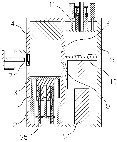
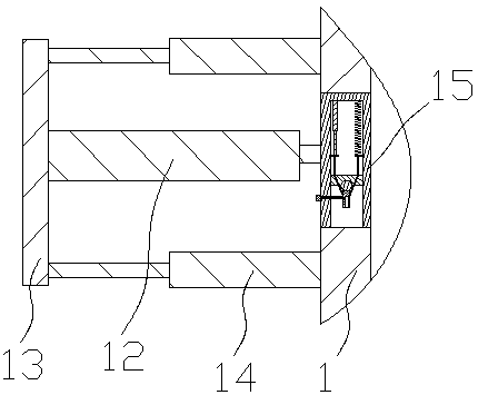
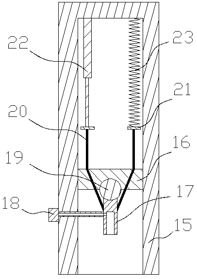
[0023] Such as Figure 1-3 As shown, the specific structure of the present invention is: a special-shaped waterway mold forming mechanism capable of avoiding waterway powder compaction, including a forming box 1, in which a forming lifting block 3 is provided through a forming lifting cylinder 2, and the forming box The upper part of 1 is provided with a laser transmitter 4 that cooperates with the forming lifting block 3 and is connected to the controller. The side of the forming box 1 is provided with a powder inlet 6 and a powder outlet 8. The forming box 1 The side opposite to the powder outlet 8 ...


PUM


Abstract

The invention relates to a special-shaped waterway mold forming mechanism capable of avoiding waterway powder compaction. The special-shaped waterway mold forming mechanism comprises a forming box, aforming lifting air cylinder and a forming lifting block; the upper part of the forming box is provided with a laser transmitter which is matched with the forming lifting block and connected to a controller; a powder feeding inlet and a powder discharging outlet are formed in the side face of the forming box; the side, opposite to the powder discharging outlet, of the forming box is provided witha scraping air blowing device; the scraping air blowing device comprises a scraping movable device and a scraping block connected with the scraping movable device; the scraping block is a cavity blockwith the lower part open, and an air blowing mounting block is arranged in a cavity; air blowing spray heads which downwards blow air are mounted on the air blowing mounting block side by side in thefront-rear direction; and the air blowing spray heads communicate with an air blowing pump on the outer side of the scraping block through air blowing pipes, and the air blowing pump is connected tothe controller. Through the design of the scraping air blowing device, after each layer of sheet body is formed, unformed powder in a waterway can be air-blown to be dispersed, the compacted state ofthe powder in the waterway is changed, and thus subsequent clean-up is convenient.

Description

technical field [0001] The invention relates to the field of special-shaped waterway molds, in particular to a special-shaped waterway mold forming mechanism capable of avoiding waterway powder compaction. Background technique [0002] Mold is called the mother of industry. More than 90% of industrial products are made from molds. Mold temperature directly affects the quality and production efficiency of injection molded products. It is mainly controlled and adjusted through the cooling system of the mold. Traditional The cooling water channel can only be processed into simple straight holes, it is difficult to achieve uniform cooling of the mold, the cooling effect is poor, and the molded products are prone to defects such as warping and uneven shrinkage, which restricts the quality and production efficiency of the molded products. It was proposed in the 1990s Conformal cooling technology, the water channel changes according to the shape of the product, can achieve uniform ...

Claims


Application Information

Patent Timeline
IPC IPC(8): B29C64/153B29C64/35B29C64/329B22F3/105B33Y30/00B33Y40/00
CPCB29C64/153B29C64/329B29C64/35B33Y30/00B33Y40/00B22F10/00B22F12/67B22F12/50B22F10/28B22F10/73Y02P10/25
Inventor 孙振忠陈盛贵
Owner DONGGUAN UNIV OF TECH
Why Eureka
Try Eureka