Crawler-type small-footage multi-angle rotating horizontal hole forming device
A hole-forming device and crawler-type technology, applied in the fields of geotechnical engineering and hydraulic engineering, can solve the problems of the influence of horizontal hole-forming quality, low efficiency of horizontal hole-forming, difficult adjustment of the footage angle, etc., and achieve good engineering application effect and simple structure. , easy to operate effect
- Summary
- Abstract
- Description
- Claims
- Application Information
AI Technical Summary
Problems solved by technology
Method used
Image
Examples
Embodiment 1
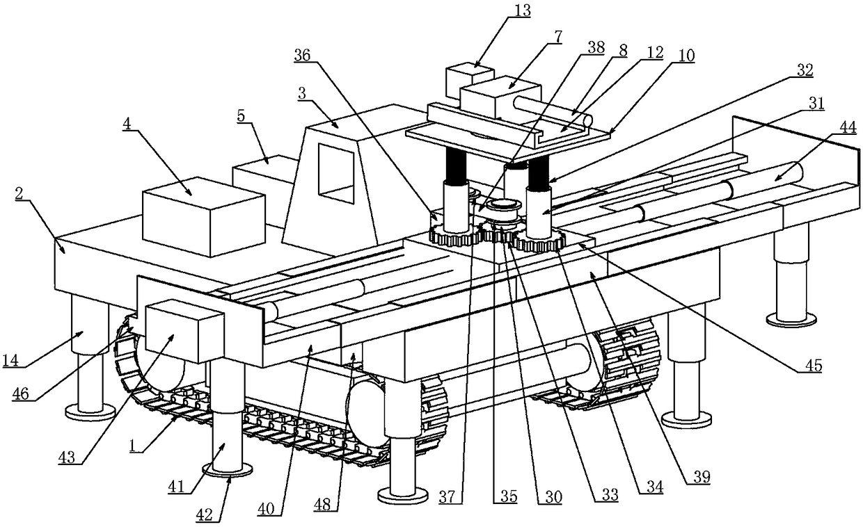
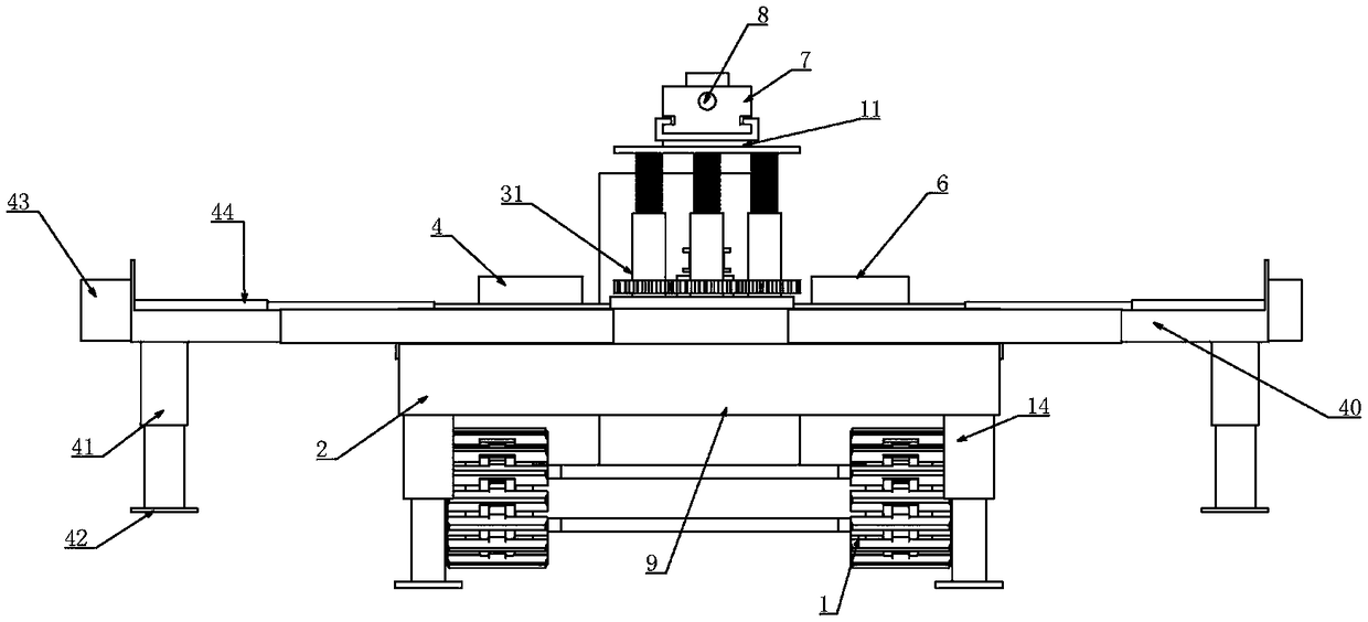
[0033] Embodiment one, combined with the attached Figure 1-11, crawler-type small-scale multi-angle rotating horizontal hole-forming device 7, including crawler-type traveling device 1, frame 2, control room 3, hydraulic control device 4, cooling device 5, power device 6, drilling rig 7 and drill pipe 8, which It is characterized in that a rotating support bearing 9 is installed on the lower part of the frame 2, and the rotating supporting bearing 9 can rotate freely at 360 degrees. The device 1 increases the attachment area between the drilling rig 7 and the ground, and is suitable for working in various terrains. The control room 3, the hydraulic control device 4, the cooling device 5 and the power unit 6 are sequentially arranged on the frame 2, and the control room 3 is connected to the drilling rig 7. The overall control of each device is equivalent to the brain center of the human body. The hydraulic control device 4 controls the hydraulic power. The cooling device 5 no...
Embodiment 2
[0037] Embodiment two, on the basis of embodiment one, in conjunction with the attached Figure 1-11 , the level detection device comprises four groups of grooves 15 uniformly distributed in the radial direction along the circumference of its horizontal center in the frame 2, the four groups of grooves 15 communicate at the horizontal center of the frame 2, and the four groups of grooves 15 is radial, and the four grooves 15 are vertically provided with a communication groove 16 at the central communication point, and the lower end of the communication groove 16 is provided with a rectangular groove 17 that is horizontally arranged and placed in the frame 2, the grooves 15, The rectangular groove 17 is connected with the communication groove 16. A support platform 18 is vertically slidably connected in the communication groove 16. The side walls of the communication groove 16 are provided with slideways, and the side walls around the support platform 18 are provided with slidew...
Embodiment 3
[0040] Embodiment three, on the basis of embodiment one, in conjunction with the attached Figure 1-11, the lifting device includes a main shaft 30 rotatably connected to the upper end of the slider 45, three sets of sleeves 31 are evenly distributed on the outer circumference of the main shaft 30 and connected to the upper end of the slider 45, and the sleeves 31 are internally threaded A telescopic rod 32, the upper end of the telescopic rod 32 is connected to the lower end surface of the lifting platform 10, the main shaft 30 is coaxially connected with a sun gear 33, and the sleeve 31 is coaxially connected with a planet meshed with the sun gear 33 Wheel 34, the coaxial sleeve on the main shaft 30 is provided with a third pulley 35, and also includes a second motor 36 connected to the upper end of the slider 45, the output shaft of the second motor 36 is coaxially sleeved with a fourth pulley 37 A second belt 38 is sleeved between the third pulley 35 and the fourth pulley ...
PUM
 Abstract
Description
Claims
Application Information
 - R&D Engineer
- R&D Manager
- IP Professional
- Industry Leading Data Capabilities
- Powerful AI technology
- Patent DNA Extraction
Browse by: Latest US Patents, China's latest patents, Technical Efficacy Thesaurus, Application Domain, Technology Topic, Popular Technical Reports.
© 2024 PatSnap. All rights reserved.Legal|Privacy policy|Modern Slavery Act Transparency Statement|Sitemap|About US| Contact US: help@patsnap.com


