
Robot grinding system with three-dimensional vision and control method thereof

A 3D vision and robotics technology, applied in the field of robotics, can solve problems such as high maintenance costs, single object-oriented products, and the impact of optical devices, and achieve the effects of improving the scope of polishing, improving environmental adaptability, and reducing equipment costs.

Pending Publication Date: 2019-03-19
716TH RES INST OF CHINA SHIPBUILDING INDAL CORP +1
View PDF0 Cites 41 Cited by
  • Summary
  • Abstract
  • Description
  • Claims
  • Application Information

AI Technical Summary

Problems solved by technology

[0004] Some people in China have conducted research on the robot automatic grinding system and achieved certain results, but most of them are still in an ideal environment and have not been practically promoted to the industrial robot site for workpiece grinding. The main problems are as follows: (1) cannot It is suitable for the production tasks of multi-variety, small batch and non-standard grinding workpieces; (2) optical devices are seriously affected by external light and cannot be applied to rough industrial grinding sites; (3) the grinding equipment is expensive and the maintenance cost is high, and the current automatic grinding Most of the equipment is in the form of special equipment, the cost of equipment research and development and production remains high, and the product is single-object-oriented, which makes it difficult to meet different grinding needs

Method used


Image

  • Robot grinding system with three-dimensional vision and control method thereof
  • Robot grinding system with three-dimensional vision and control method thereof
  • Robot grinding system with three-dimensional vision and control method thereof

Examples


Embodiment Construction

[0049] The following will clearly and completely describe the technical solutions in the embodiments of the present invention with reference to the accompanying drawings in the embodiments of the present invention. Obviously, the described embodiments are only some, not all, embodiments of the present invention. Based on the embodiments of the present invention, all other embodiments obtained by persons of ordinary skill in the art without creative efforts fall within the protection scope of the present invention.

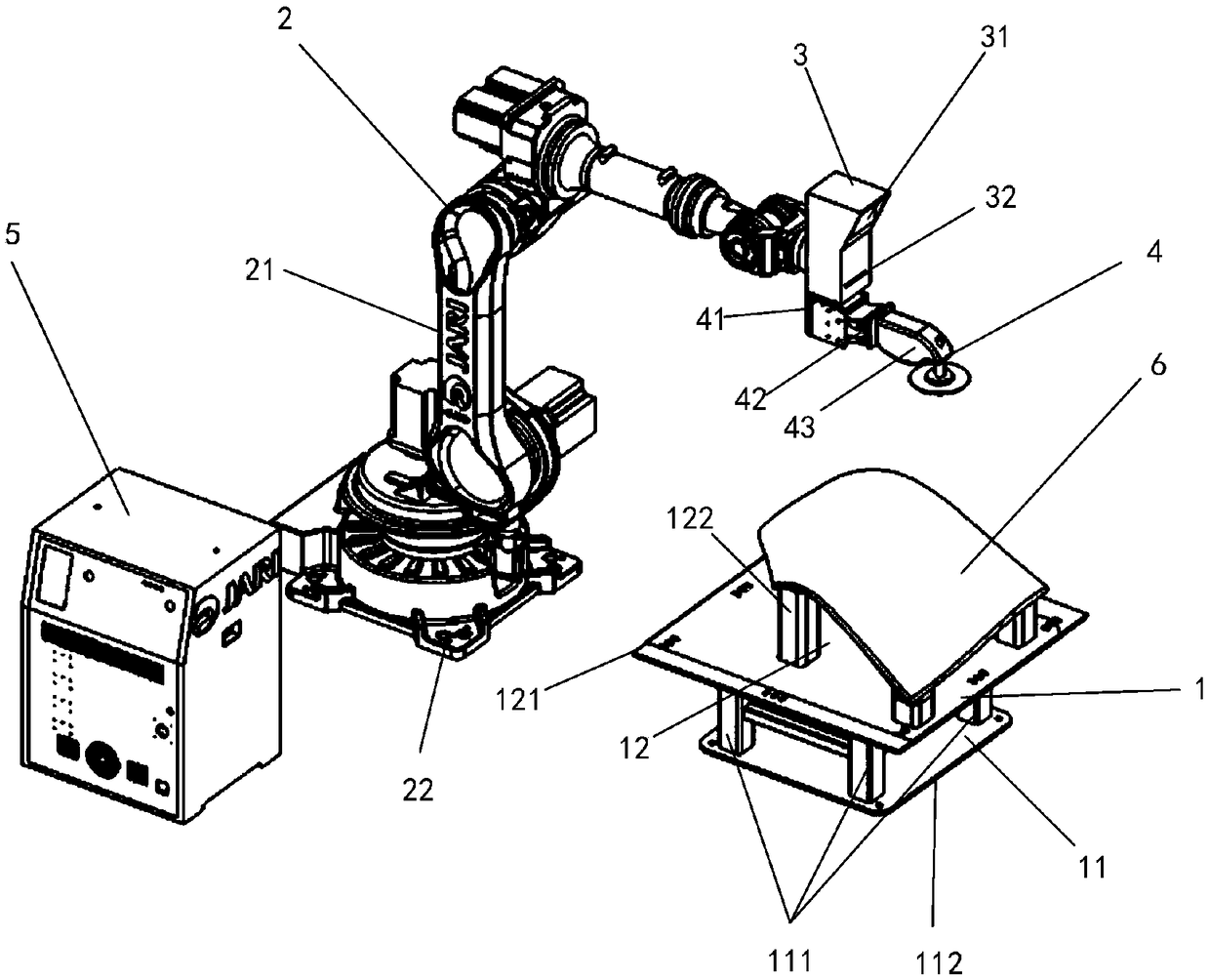
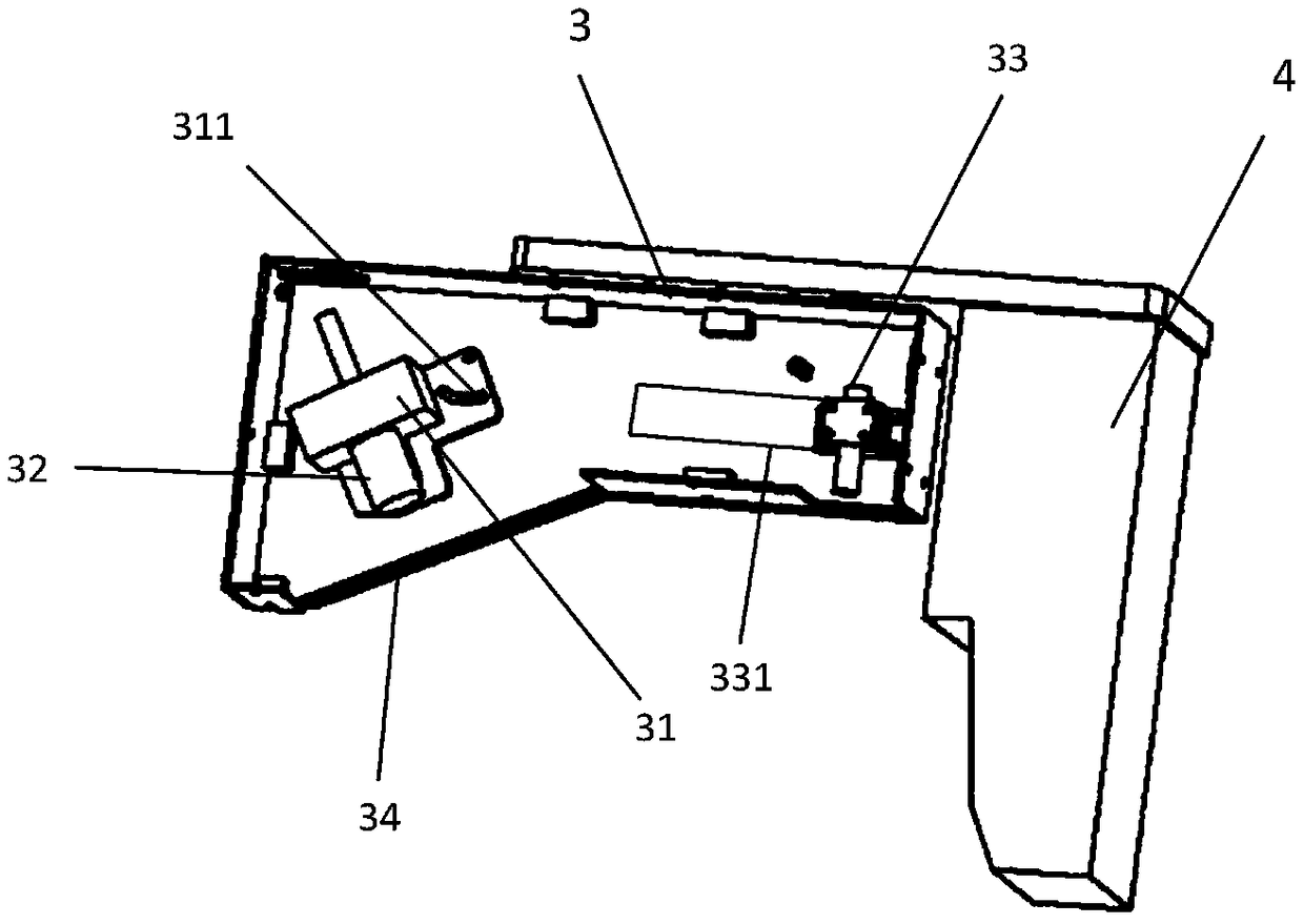
[0050] Such as figure 1 As shown, the present invention provides a robot grinding system with three-dimensional vision, including a workpiece fixing device 1 , a grinding robot 2 , an optical device 3 , a pneumatic grinding device 4 , and a power supply and control device 5 . The workpiece fixing device 1 is responsible for supporting and fixing the curved surface workpiece 6 at the corresponding position. By moving the position of the support column 122, the stabl...


PUM


Abstract

The invention discloses a robot grinding system with three-dimensional vision and a control method thereof. The robot grinding system comprises a workpiece fixing device, a grinding robot, an opticaldevice, pneumatic grinding equipment, a power supply and a control device. The control method of the robot grinding system with the three-dimensional vision comprises the steps that the grinding robotdrives the optical device to horizontally scan a curved surface workpiece; a laser image collected by a 3D camera is transmitted to the control device in the power supply and the control device; thecontrol device performs the three-dimensional point cloud processing to the image obtained by the 3D camera by using a corresponding function, and the preliminary filtering denoising is carried out; the point cloud segmentation and a slice algorithm are used for performing the further processing on the obtained three-dimensional point cloud; and processing results are analyzed and sent to the control device according to rules, and the robot is driven to perform the wholly grinding operation on the curved surface workpiece in the correct attitude. The robot grinding system with three-dimensional vision and the control method thereof are mainly used for automatic grinding in the field of curved surface structure manufacturing, and the production efficiency and production quality are improvedby improving the automation degree of the industrial grinding field.

Description

technical field [0001] The invention relates to the technical field of robots, in particular to a robot grinding system with three-dimensional vision and a control method thereof. Background technique [0002] The traditional grinding of curved surface structure workpieces is characterized by high processing difficulty, low automation, long time consumption, high cost, and large dust. It is usually a difficult point in the manufacturing process of ships, automobiles, aerospace and other fields. In particular, it is more difficult to control the production and grinding process of special-shaped surfaces, multi-curvature surfaces, and non-rational surfaces (such as turbine blades, hulls, and casings). Subjective inspections are often carried out based on experience. Therefore, the qualified rate of one-time processing is low and there are many shortcomings in the grinding process. Including: (1) Due to the harsh working environment at the grinding site, sparks and dust will ca...

Claims


Application Information

Patent Timeline
IPC IPC(8): B24B19/00B24B41/06B24B49/12B24B51/00G06K9/00G06K9/20
CPCB24B19/00B24B41/06B24B49/12B24B51/00G06V10/143G06F2218/00
Inventor 王兴华曹为理蔡明智范小卿江舒
Owner 716TH RES INST OF CHINA SHIPBUILDING INDAL CORP
Learn More