Metal plate cutting machining system
A technology for cutting and processing metal sheets, which is applied in metal processing, metal processing equipment, metal processing machinery parts, etc., can solve the problems of poor adjustability and high maintenance cost, and achieve easy maintenance, low maintenance cost and strong adjustability Effect
- Summary
- Abstract
- Description
- Claims
- Application Information
AI Technical Summary
Problems solved by technology
Method used
Image
Examples
Embodiment 1
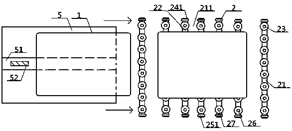
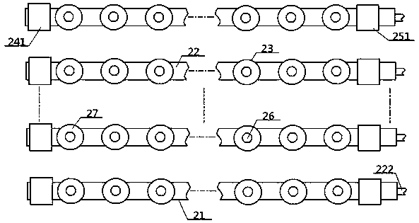
[0050] see Figure 1 to Figure 5 , a metal plate cutting processing system, including a plate feeding unit 5 and a cutting unit 2, the outlet of the plate feeding unit 5 communicates with the feeding port of the cutting unit 2, and above the cutting unit 2 is suspended Cutting machine; the cutting unit 2 includes a plurality of strip support seats 21 with the same structure, adjacent strip support seats 21 are parallel to each other, and inter-seat gaps 211 are provided between adjacent strip support seats 21 The strip support seat 21 includes a strip matrix 22, No. 1 lifting device 24, No. 2 lifting device 25, and a plurality of supporting monomers 23, and the supporting monomers 23 include metal balls 26 and plastic ball seats 27. The top of the plastic ball seat 27 is connected with the bottom end of the metal ball 26, the bottom end of the plastic ball seat 27 is connected with the top of the strip substrate 22, and the two ends of the strip substrate 22 are connected with...
Embodiment 2
[0052] Basic content is the same as embodiment 1, the difference is:
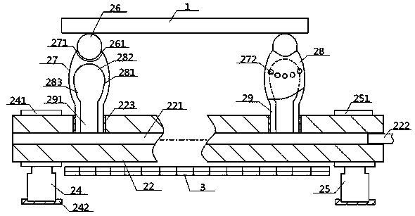
[0053] The elongated base 22 is a hollow structure, and the inside of the elongated base 22 is provided with a coaxial elongated cavity 221, one end of the elongated cavity 221 is flush with the end face of the elongated base 22, and the elongated cavity The other end of 221 is connected with the intake pipe head 222; the plastic ball seat 27 includes a spherical portion 28 and a fixed portion 29, the side of the spherical portion 28 is a spherical structure, and the side of the spherical portion 28 is provided with a plurality of Air vent 272, the top of spherical portion 28 is connected with the bottom of metal ball 26, the bottom of spherical portion 28 is connected with the top of fixed portion 29, and the bottom of fixed portion 29 passes through the top surface of elongated substrate 22 In contact with the strip cavity 221, the inside of the spherical portion 28 is provided with a spherical cavity 281...
Embodiment 3
[0055] Basic content is the same as embodiment 2, the difference is:
[0056] Described spherical cavity 281 comprises hemispherical body cavity 282 and conical frustum cavity 283, and the bottom end of described hemispherical body cavity 282 communicates with the top of fixed cavity 291 after passing through conical frustum cavity 283, and the top of conical frustum cavity 283 is wider than its bottom. end, and the vent hole 272 is arranged along the intersection line of the hemispherical cavity 282 and the conical cavity 283 . Preferably, the side circumference of the spherical portion 28 is an ellipsoid structure.
PUM
 Abstract
Description
Claims
Application Information
 - R&D
- Intellectual Property
- Life Sciences
- Materials
- Tech Scout
- Unparalleled Data Quality
- Higher Quality Content
- 60% Fewer Hallucinations
Browse by: Latest US Patents, China's latest patents, Technical Efficacy Thesaurus, Application Domain, Technology Topic, Popular Technical Reports.
© 2025 PatSnap. All rights reserved.Legal|Privacy policy|Modern Slavery Act Transparency Statement|Sitemap|About US| Contact US: help@patsnap.com


