
Skin beauty suture device

A suturing device and epidermis technology, applied in the field of medical devices, can solve the problems of inaccurate control of the position of penetrating the skin, long suturing time of large trauma surgery, uneven force on wound tissue, etc., so as to reduce the risk of anesthesia and improve suturing. The effect of operation accuracy and improvement of suturing efficiency

Inactive Publication Date: 2019-03-19
付亚坤
View PDF13 Cites 1 Cited by
  • Summary
  • Abstract
  • Description
  • Claims
  • Application Information

AI Technical Summary

Problems solved by technology

[0004] (1) When suturing with smooth lines, the suturing efficiency is low, and major trauma surgery leads to long suturing time for major trauma surgery, and at the same time, the time required for anesthesia is also prolonged, which increases the safety risk of patients during surgery;
[0005] (2) In the experimental suture needle surgery, it is necessary to use surgical needle forceps to clamp the suture needle to penetrate the skin, and each suture needs to be loosened once, resulting in low suture efficiency and inaccurate control of the position of the skin penetration. The sewing precision is not high;
The smooth thread mainly used in the existing suture operation has disadvantages such as uneven stress on the wound tissue after suturing the wound, and prone to thread knot reaction, which will leave large scars on large wounds such as caesarean section, and it is difficult to eliminate in subsequent life

Method used


Image

  • Skin beauty suture device
  • Skin beauty suture device
  • Skin beauty suture device

Examples


Embodiment Construction

[0028] In order to make the technical means, creative features, goals and effects achieved by the present invention easy to understand, the present invention will be further described below in conjunction with specific illustrations. It should be noted that, in the case of no conflict, the embodiments in the present application and the features in the embodiments can be combined with each other.

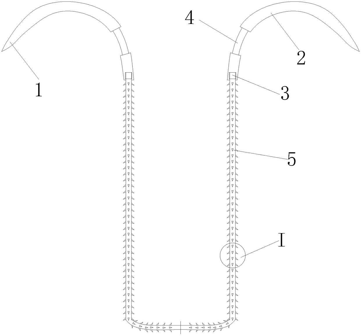
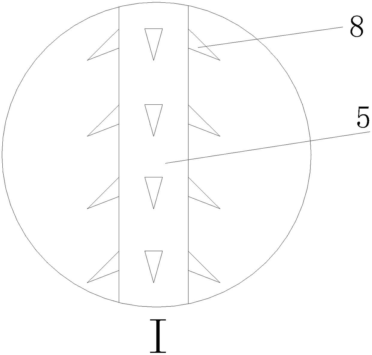
[0029] Such as Figure 1 to Figure 6 As shown, an epidermis cosmetic suturing device includes: a suture needle assembly, a thumb fastening ring and a forefinger fastening ring, the suture needle assembly includes a barbed thread 5, and the outer side of the barbed thread 5 is covered with a wire sleeve 51 , the front end of the barbed thread 5 is connected with a suture needle, the suture needle is bent into a small semicircle, and the suture needle includes the needle waist 2, the needle point 1 provided at the front end of the needle waist 2 and the needle fixed at the rear of the ...


PUM


Abstract

The invention relates to a skin beauty suture device. The device comprise a suture needle assembly, a thumb fastening ring and an index finger fastening ring, the suture needle assembly comprises a barb wire, suture needles are connected to the two ends of the barb wire, each suture needle is bent to form a small half circle, and comprises a needle waist, a needle tip arranged at the front end ofthe needle waist and a needle end fixedly connected with the rear portion of the needle waist, the needle waists and the needle ends are each shaped like a cylinder, a threading slot is formed in therear side of each needle end, the wire head and the wire end of the barb wire are arranged in the threading slots of the two suture needles respectively, cylindrical clamping bars used for clamping are arranged on the rear sides of the needle waists, the diameter of the cylindrical clamping bars is smaller than that of the needle waists, two barb belts with opposite directions are symmetrically arranged from the central location of the barb wire, each barb belt is provided with four rows of barbs, and the included angles of every two adjacent rows of barb belts is 90 degrees. Accordingly, thefunctions that in tissue suture surgery, the surgery time is shortened, postoperative scars are reduced, and the device has the advantages of being high in use efficiency, small in postoperative scarand the like.

Description

technical field [0001] The invention relates to the technical field of medical devices, in particular to an epidermis cosmetic suturing device. Background technique [0002] Postoperative tissue suturing is an essential part of large-trauma operations such as closing the cavity. During tissue suturing, physicians use needles to drive sutures to suture wounds. Now the most common method of suturing is to use a needle to drive smooth threads. During surgery, only one doctor can suture a wound at the same time. [0003] The existing surgical suturing device mainly has the following problems: [0004] (1) When suturing with smooth lines, the suturing efficiency is low, and major trauma surgery leads to long suturing time for major trauma surgery, and at the same time, the time required for anesthesia is also prolonged, which increases the safety risk of patients during surgery; [0005] (2) In the experimental suture needle surgery, it is necessary to use surgical needle force...

Claims


Application Information

Patent Timeline
IPC IPC(8): A61B17/06
CPCA61B17/06061A61B17/06066A61B17/06166A61B2017/06176
Inventor 付亚坤
Owner 付亚坤
Learn More