
Bearing bush

A technology for bushings and outer sleeves, applied to springs, springs, springs/shock absorbers made of plastic materials, etc., which can solve problems such as complex outlines of outer sleeves

Inactive Publication Date: 2019-03-15
VIBRACOUSTIC GMBH
View PDF5 Cites 4 Cited by
  • Summary
  • Abstract
  • Description
  • Claims
  • Application Information

AI Technical Summary

Problems solved by technology

The reason for this is usually the complex contour of the outer sleeve, which can be easily and inexpensively displayed with the aid of plastic

Method used


Image

  • Bearing bush
  • Bearing bush
  • Bearing bush

Examples


Embodiment Construction

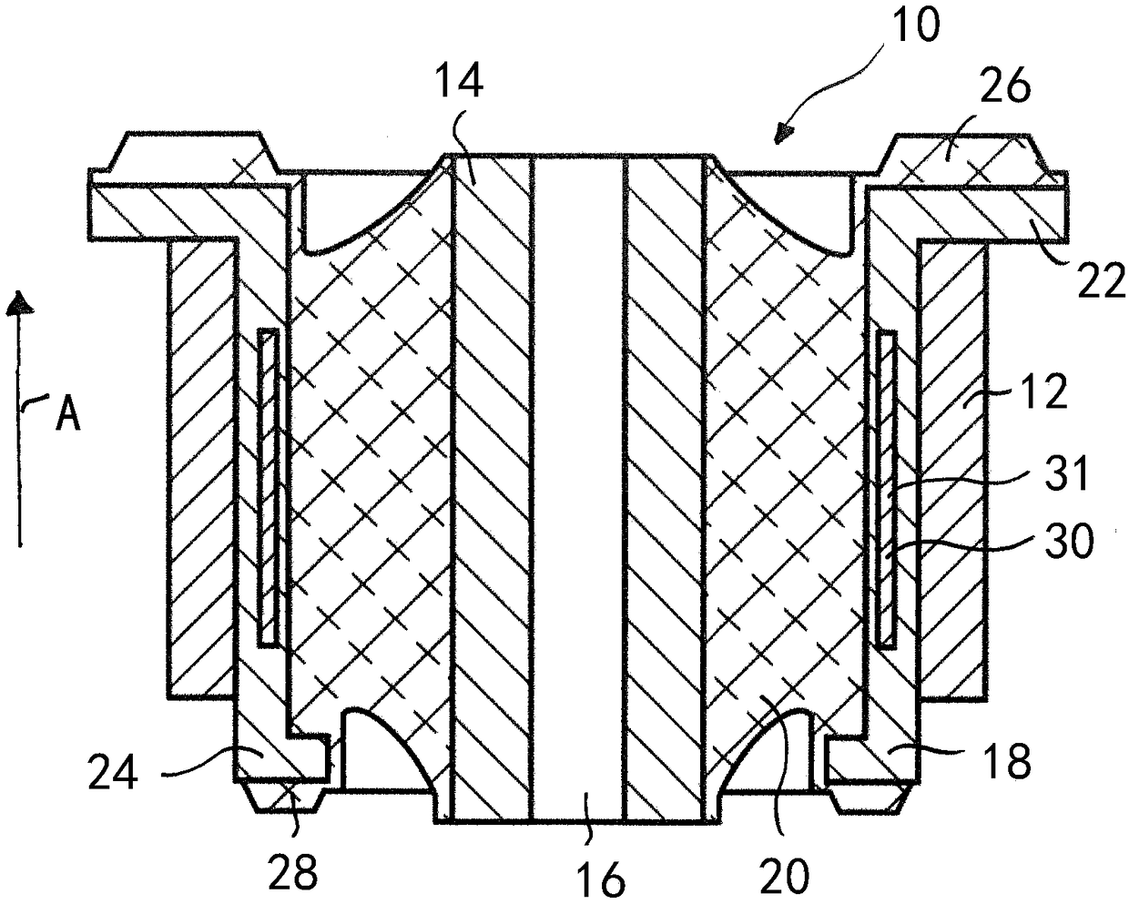
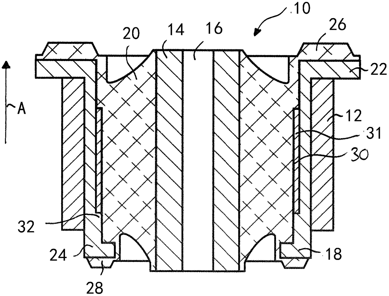
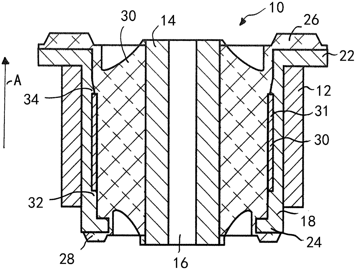
[0040] figure 1 Shown is a bearing bushing 10 which is pressed into a receiving hole 12 of a motor vehicle chassis (not shown). The bushing 10 has an inner core 14 with a central hole 16 for connecting the bearing bushing 10 to a motor vehicle component not shown, an outer sleeve 18 surrounding the inner core 14 and connecting the inner core 14 and outer sleeve 18 interconnected elastomer 20 .

[0041] The outer sleeve 18 is made of plastic or fibre-reinforced plastic and has at a first end a radially outwardly pointed first flange portion 22 and a radially inwardly pointed second flange portion 24, the first flange portion 22 adjoining to receive end of hole 12.

[0042] The elastomer 20 is integrally connected to the outer sleeve 18, in particular by vulcanization, and has a first axial stop 26 in the area of ​​the first flange part 22 and a second axial stop 26 in the area of ​​the second flange part 24. Axial stop 28 .

[0043] as well figure 1 As shown, the support 3...


PUM


Abstract

The invention relates to a bearing bush (10) which is to be mounted in a receiving lug (12) in a chassis and which comprises a core (14), an outer sleeve (18) that surrounds the core (14) and is madeof a first material, and an elastomer part (20) that connects the core (14) and the outer sleeve (18) to each other, a supporting element (30) which is made of a second material radially supporting the outer sleeve (18) when the latter is pressed into the receiving lug (12).

Description

technical field [0001] The invention relates to a bearing bush for pressing into a receiving hole of a chassis, especially a subframe, the bearing bush comprising an inner core, an outer sleeve surrounding the inner core and made of a first material, and said inner core The core and the outer sleeve are interconnected elastomers. Background technique [0002] Bushings of the type mentioned in the introduction are used in motor vehicle chassis, for example, to damp forces or shocks that occur when driving over uneven ground, to isolate incoming vibrations and thus to increase driving comfort. A conventional bearing bushing, which may also be referred to as an elastomeric bushing, has an inner core, an outer sleeve surrounding the inner core, and an elastomer interconnecting the inner core and outer sleeve. [0003] To fix the bearing bushing in the chassis, the bearing bushing is pressed into the receiving bore. In the case of the use of metallic material for the outer slee...

Claims


Application Information

Patent Timeline
Patent Type & Authority Applications(China)
IPC IPC(8): F16F1/387F16F1/38
CPCF16F1/3863F16F1/3876
Inventor P·维尔纳H·卡尔多斯
Owner VIBRACOUSTIC GMBH
Learn More