
Liquid crystal displaying panel

A liquid crystal display panel and substrate technology, which is applied in nonlinear optics, instruments, optics, etc., can solve the problems of light leakage at the edge of the panel, and achieve the effects of reducing phase delay, reducing stress, and improving light leakage at the edge

Active Publication Date: 2019-03-15
SHENZHEN CHINA STAR OPTOELECTRONICS SEMICON DISPLAY TECH CO LTD
View PDF9 Cites 4 Cited by
  • Summary
  • Abstract
  • Description
  • Claims
  • Application Information

AI Technical Summary

Problems solved by technology

[0004] The invention provides a liquid crystal display panel to solve the technical problem that light leakage is likely to occur at the edge of the panel when the liquid crystal display panel is bent

Method used


Image

  • Liquid crystal displaying panel
  • Liquid crystal displaying panel
  • Liquid crystal displaying panel

Examples


Embodiment 1

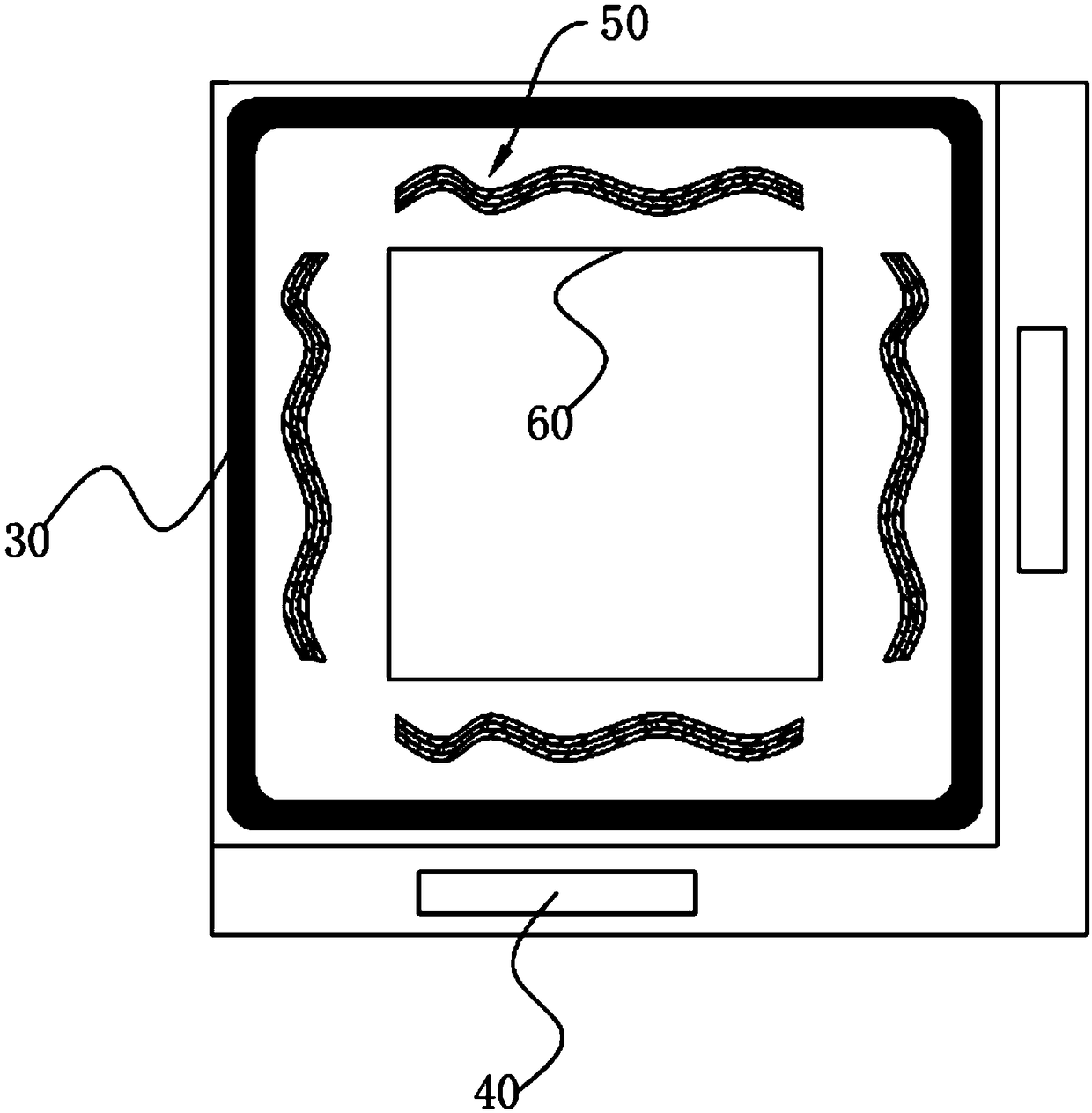
[0031] A liquid crystal display panel, such as figure 1 As shown, the liquid crystal display panel includes a driver chip 40, a color filter substrate 10, a thin film transistor substrate 20, and a sealant 30 disposed between the color filter substrate 10 and the thin film transistor substrate 20. The sealant 30 A liquid crystal layer (not shown in the figure) is disposed in the sealed cavity formed with the color filter substrate 10 and the thin film transistor substrate 20 .

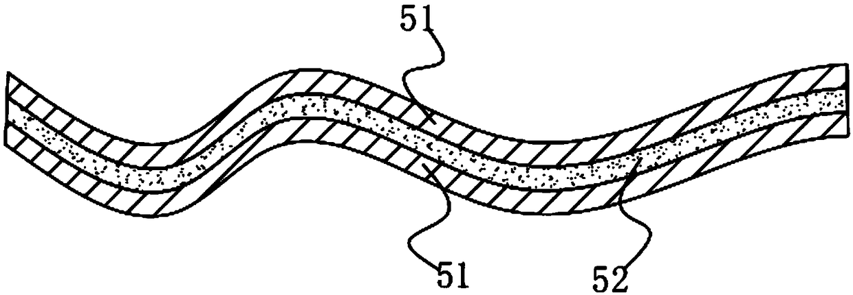
[0032] Among them, such as figure 1 with figure 2 As shown, an elastic buffer structure 50 distributed around the display area 60 is also provided between the color filter substrate 10 and the thin film transistor substrate 20 , and the elastic buffer structure 50 is located inside the sealant 30 .

[0033] Specifically, the elastic buffer structure 50 includes a first elastic member fixedly arranged on the color filter substrate 10 and a second elastic member fixedly arranged on the thin film trans...

Embodiment 2

[0044] A liquid crystal display panel, such as Figure 4 As shown, it differs from Embodiment 1 only in that the number of second elastic strips 52 included in the second elastic member is different.

[0045] Specifically, the second elastic member includes at least two second elastic strips 52 arranged in parallel.

[0046] It should be noted, Figure 4 2 only illustrates the case where the second elastic member includes two second elastic strips 52 , in a specific implementation, the second elastic member may also include three, four or more second elastic strips 52 .

Embodiment 3

[0048] A liquid crystal display panel, such as Figure 5 As shown, it differs from Embodiment 1 only in that the number of second elastic strips 52 included in the second elastic member and the number of first elastic strips 51 included in the first elastic member are different.

[0049] Specifically, the second elastic member includes at least two second elastic strips 52 arranged in parallel and spaced apart, and the first elastic member includes a first elastic strip 51 .

[0050] Wherein, the shape of the gap between the adjacent second elastic strips 52 is adapted to the shape of the first elastic piece, and when the first elastic piece engages with the second elastic piece, the first elastic piece The elastic piece is located in the gap between the adjacent second elastic strips 52 .

[0051] It should be noted, Figure 5 2 only illustrates the case where the second elastic member includes two second elastic strips 52 , in a specific implementation, the second elastic ...


PUM

PropertyMeasurementUnit
widthaaaaaaaaaa

Abstract

The invention provides a liquid crystal display panel. The liquid crystal display panel comprises a colorful diaphragm substrate, a thin-film transistor substrate and sealing glue and an elastic buffering structure which are arranged between the colorful diaphragm substrate and and the thin-film transistor substrate; the elastic buffering structure comprises a first elastic member which is fixedlyarranged on the colorful diaphragm substrate and a second elastic member which is fixedly arranged on the thin-film transistor substrate, and the first and second elastic members are clamped after the colorful diaphragm substrate and the thin-film transistor substrate are aligned and assembled. The liquid crystal display panel has the advantages that when the liquid crystal display panel is bent,the dislocation of upper and lower substrates of the edge of the liquid crystal display panel is reduced on one hand due to the clamping of the first and second elastic members and the buffering on stress, on the other hand, part of the stress at the edges of the liquid crystal display panel is stored by the buffering effect of the elastic buffering structure, so that the stress at the edges of the liquid crystal display panel is greatly reduced, phase-position delay at the edge of the liquid crystal display panel is reduced, and the light leakage of the edges is greatly improved.

Description

technical field [0001] The invention relates to the field of display technology, in particular to a liquid crystal display panel. Background technique [0002] TFT-LCD (Thin Film Transistor Liquid Crystal Display) is very popular because of its advantages of high quality and low price, light weight, easy to carry, long service life, clear picture and high reliability. Because the conventional TFT-LCD uses a glass substrate, the glass substrate has a certain rigidity, so the bending radius is limited and cannot meet the requirements of multiple curvatures or small bending radii. Therefore, a flexible LCD is proposed. Flexible LCD almost inherits all the advantages of rigid LCD, and also has the advantages of anti-drop, light weight, and flexibility. [0003] However, whether it is a flexible LCD or a traditional rigid LCD, when the panel is bent, the edge of the panel will be subject to excessive stress, resulting in relatively large dislocations between the upper and lower ...

Claims


Application Information

Patent Timeline
Patent Type & Authority Applications(China)
IPC IPC(8): G02F1/1339
CPCG02F1/1339
Inventor 李柱辉
Owner SHENZHEN CHINA STAR OPTOELECTRONICS SEMICON DISPLAY TECH CO LTD
Learn More