
A carbon dioxide injection device for carbon dioxide flooding

A carbon dioxide and injection device technology, which is applied in wellbore/well components, climate sustainability, and production fluids, etc., can solve the problems of inconvenient length adjustment of gas injection pipelines, affecting the oil production effect of oil and gas wells, and affecting the use range of devices, etc. The effect of improving the scope of use, novel design and high practical value

Inactive Publication Date: 2020-11-06
CHINA UNIV OF PETROLEUM (EAST CHINA)
View PDF6 Cites 1 Cited by
  • Summary
  • Abstract
  • Description
  • Claims
  • Application Information

AI Technical Summary

Problems solved by technology

[0003] There are many problems in the injection process of carbon dioxide used in oil and gas wells. For example, in the process of carbon dioxide injection in the existing carbon dioxide device, the process of injecting carbon dioxide into oil and gas wells cannot be continuously injected, which greatly affects the oil production effect in oil and gas wells. At the same time, when the device is in use, it needs to be manually transported and adjusted, which greatly increases the workload of the laborers, and the existing gas injection pipeline is not convenient for length adjustment, which affects the use range of the device and is not easy to use.

Method used


Image

  • A carbon dioxide injection device for carbon dioxide flooding
  • A carbon dioxide injection device for carbon dioxide flooding
  • A carbon dioxide injection device for carbon dioxide flooding

Examples


Embodiment Construction

[0026] The technical solutions in the embodiments of the present invention will be clearly and completely described below with reference to the accompanying drawings in the embodiments of the present invention. Obviously, the described embodiments are only a part of the embodiments of the present invention, but not all of the embodiments. Based on the embodiments of the present invention, all other embodiments obtained by those of ordinary skill in the art without creative efforts shall fall within the protection scope of the present invention.

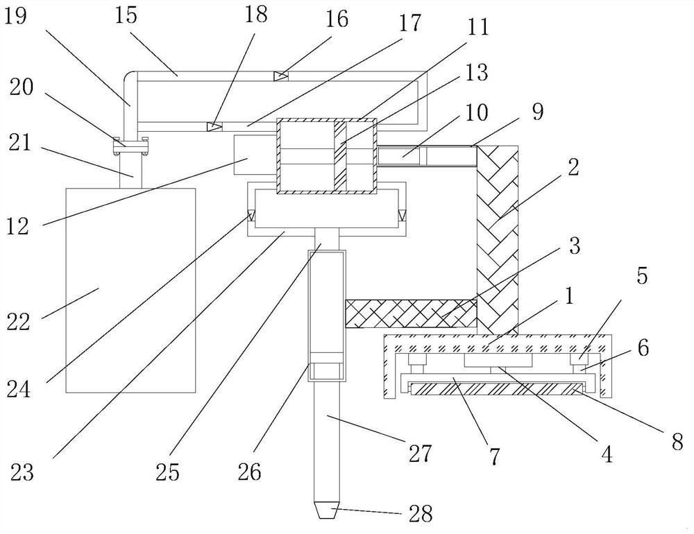
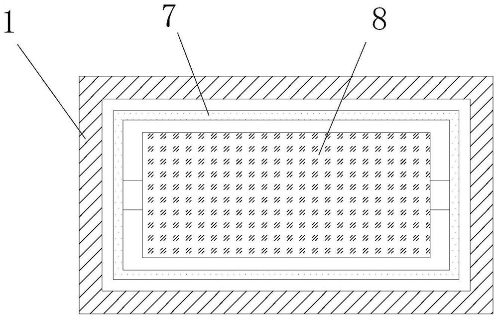
[0027] see Figure 1-3 As shown, a carbon dioxide injection device for carbon dioxide flooding includes a fixed seat 1, a support column 2, a fixed column 3, a moving mechanism and a gas injection mechanism;

[0028] A support column 2 is fixedly connected to the middle part of the top side of the fixed seat 1, and a fixed cylinder 9 is fixedly connected to one side of the top end of the support column 2; Fixed connection, the set ex...


PUM


Abstract

The invention discloses a carbon dioxide injection device for carbon dioxide oil displacement, which comprises a fixed seat, a supporting column, a fixing column, an electro-hydraulic push rod, a connecting cylinder, a connecting rod, a supporting seat, a rolling cylinder, a fixing cylinder, a moving rod, an exhaust shell, an electric push rod, a piston and a scale mark, a first air inlet pipe, afirst one-way valve, a second air inlet pipe, a second one-way valve, a main air inlet pipe, a flange, an exhaust pipe, a carbon dioxide storage tank, an air outlet pipe, a third one-way valve, a connecting air pipe, a first air guide pipe, a second air guide pipe and a conical air pipe head. The carbon dioxide injection device for carbon dioxide oil displacement has a simple structure, is convenient for continuously injecting carbon dioxide gas, ensures stable and orderly injection of the carbon dioxide gas at the same time, improves the continuous supply efficiency of the carbon dioxide gas;the support seat is pushed by the electro-hydraulic push rod pushing up the fixing seat to adjust the rolling wheel, so that a worker can conveniently push and move the device, and the labor intensity of the worker moving device is greatly reduced.

Description

technical field [0001] The invention relates to a carbon dioxide injection device, in particular to a carbon dioxide injection device for carbon dioxide flooding oil, and belongs to the technical field of carbon dioxide flooding oil application. Background technique [0002] The carbon dioxide flooding technology is the technology of injecting carbon dioxide into the oil layer to improve the oil recovery rate of the oil field; when the carbon dioxide and the crude oil in the formation first contact, the miscible phase cannot be formed, but under the conditions of suitable pressure, temperature and crude oil composition, the carbon dioxide can form a miscible phase leading edge. Supercritical fluids will extract heavier hydrocarbons from crude oil and continuously condense the gas at the displacement front. [0003] There are many problems in the process of carbon dioxide injection for oil and gas wells. For example, in the process of carbon dioxide injection in existing car...

Claims


Application Information

Patent Timeline
Patent Type & Authority Patents(China)
IPC IPC(8): E21B43/16
CPCE21B43/164Y02P90/70
Inventor 柏宗宪王杰祥李伟玉李晟武婧雯赵聪
Owner CHINA UNIV OF PETROLEUM (EAST CHINA)
Learn More