
Double-beam laser mirror image welding method

A welding method and double-beam technology, applied in laser welding equipment, welding equipment, metal processing equipment, etc., can solve the problems of low process manufacturing efficiency, inconvenient operation of turning the rudder surface, inconvenient automatic welding, etc., to ensure the symmetry of temperature changes , Improve welding efficiency and facilitate automation

Inactive Publication Date: 2019-03-15
SHANGHAI SPACE PRECISION MACHINERY RES INST
View PDF13 Cites 6 Cited by
  • Summary
  • Abstract
  • Description
  • Claims
  • Application Information

AI Technical Summary

Problems solved by technology

Specifically, the current main electron beam or laser beam manufacturing methods are single heat source welding. In order to control deformation, it is necessary to continuously flip the rudder surface back and forth during spot welding and formal welding. It is also very inconvenient to realize the automatic welding process, especially electron beam welding requires a vacuum chamber, and it is very inconvenient to flip the rudder surface operation
At the same time, the asymmetric welding heat cycle process also means that the manufacturing accuracy is limited. Sometimes, in order to improve the accuracy, it is necessary to turn over the rudder surface as much as possible to achieve the symmetry of the heat input. The flipping and uneven forced cooling also significantly increase the uncertainty of manufacturing precision control

Method used


Image

  • Double-beam laser mirror image welding method
  • Double-beam laser mirror image welding method

Examples


Embodiment Construction

[0037] The present invention will be described in detail below in conjunction with specific embodiments. The following examples will help those skilled in the art to further understand the present invention, but do not limit the present invention in any form. It should be noted that those skilled in the art can make several changes and improvements without departing from the concept of the present invention. These all belong to the protection scope of the present invention.

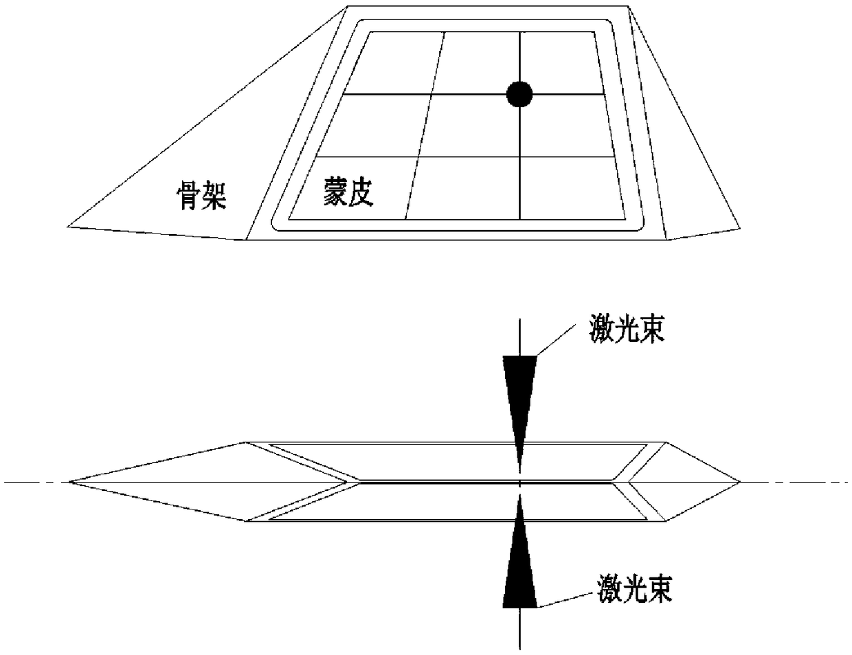
[0038] According to a double-beam laser image welding method provided by the present invention, the first part and the second part to be welded are used, including the following steps:

[0039] Welding preparation step: pretreatment of the first part and the second part;

[0040] Fixing step: performing combined mechanical assembly and spot welding of the first component and the second component;

[0041] Welding step: the first part and the second part are welded through formal laser welding;

[0042...


PUM


Abstract

The invention provides a double-beam laser mirror image welding method. The method aims at solving the problems that existing welding manufacturing is not high in precision, and low in efficiency, andautomation is not convenient to realize. According to the new assembly, welding and cooling scheme, an assembly method in a vertical position is adopted to replace an assembly method through which welding is conducted while a blocker is pasted, so that a large amount of repeated rudder surface turnover work is omitted; meanwhile, continuous welding after one-time clamping is achieved, the production process is greatly simplified, not only the welding efficiency is greatly improved, but also the automation of the welding process is more convenient to realize. By adopting a double-beam laser mirror image synchronous welding process, single-surface welding of a single heat source is replaced, high symmetry is realized in the heat cycle process, and the welding manufacturing precision can begreatly improved; and after the welding of a rudder surface is completed, the rudder surface of a titanium alloy skin skeleton is vertically placed or hung, the rudder surface is cooled to the room temperature through free radiation, the temperature change symmetry of a heat cycle of the rudder surface is further ensured, and the welding manufacturing precision is further improved.

Description

technical field [0001] The invention relates to the field of laser welding, in particular to a double-beam laser mirror image welding method, in particular to a welding method for a titanium alloy skin skeleton rudder surface. Background technique [0002] Titanium alloy skinned skeleton structure rudder surfaces have been widely used in aerospace products due to a series of advantages such as high performance, light weight and forward center of gravity. For example, patent documents CN103522022A, CN104858542A, CN106425309A, etc. have carried out beneficial research on the manufacture of titanium alloy skin skeleton structure. Not only have laser welding and electron beam welding been studied in terms of process methods, but also better assembly relationships such as inlays have been proposed. [0003] But above-mentioned prior art still exists certain deficiency. As the flight speed of tactical weapons is getting faster and faster, the manufacturing accuracy index of the r...

Claims


Application Information

Patent Timeline
Patent Type & Authority Applications(China)
IPC IPC(8): B23K26/21B23K26/60B23K26/70
CPCB23K26/21B23K26/60B23K26/702
Inventor 胡佩佩张登明欧阳自鹏孙锡建沈义平曹熙勇李中权
Owner SHANGHAI SPACE PRECISION MACHINERY RES INST
Learn More