Optical lens detection device and method

A technology of optical lenses and testing equipment, which is applied in the direction of mechanical thickness measurement, etc., can solve the problems of optical lens damage detection accuracy, etc., and achieve the effects of avoiding optical lens damage, accurate and effective detection results, and strong practicability

Pending Publication Date: 2019-03-12
淄博朗斯光电有限公司
View PDF16 Cites 6 Cited by
  • Summary
  • Abstract
  • Description
  • Claims
  • Application Information

AI Technical Summary

Problems solved by technology

[0004] The object of the present invention is to provide a kind of optical lens detection equipment and detection method, to solve the problem that optical lens detection is easy to cause damage and detection accuracy is poor

Method used


Image

  • Optical lens detection device and method
  • Optical lens detection device and method

Examples


Embodiment 1

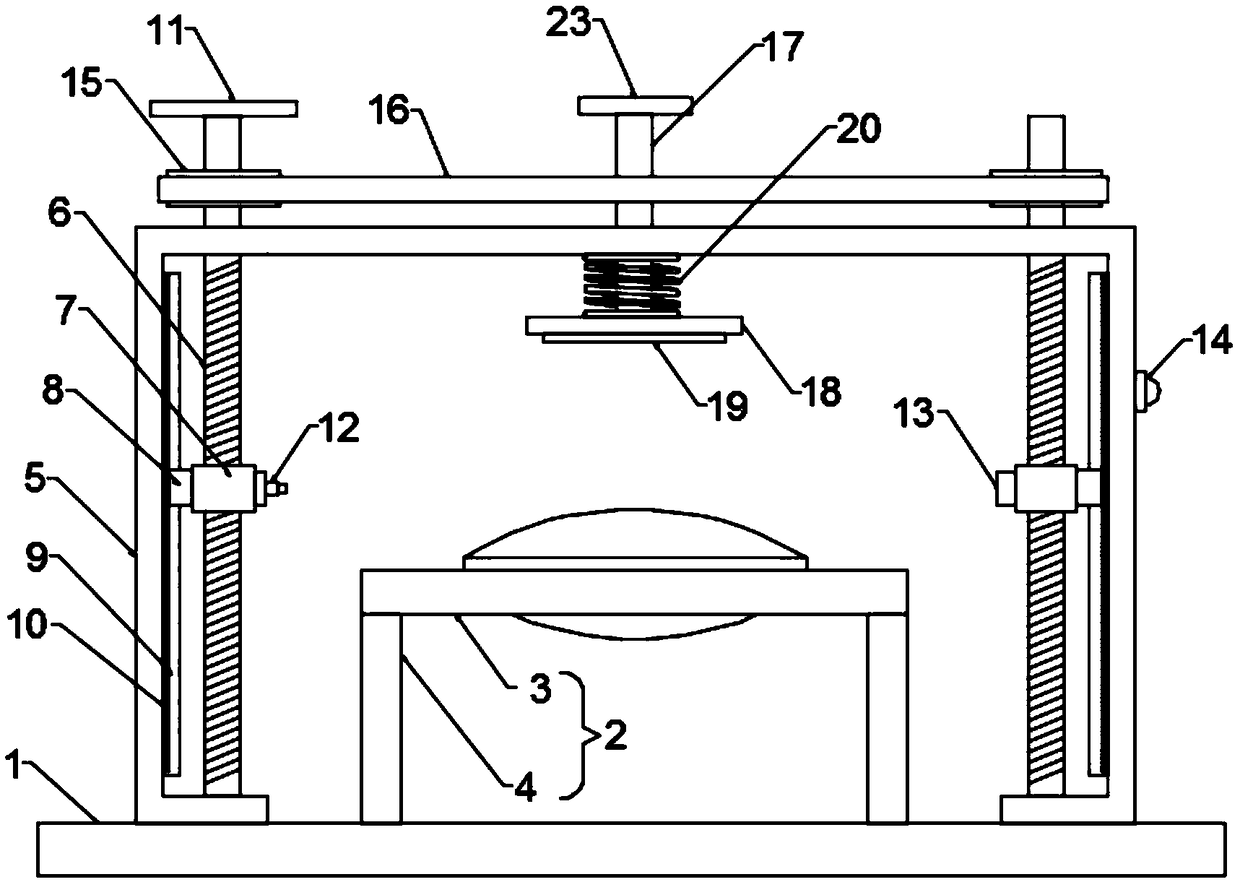
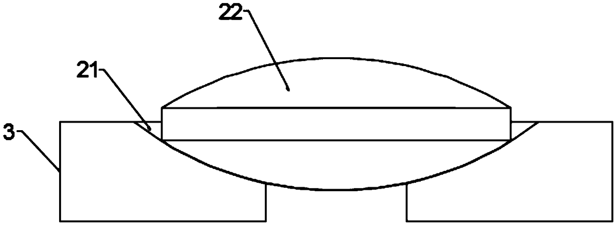
[0023] see figure 1 and 2 , in an embodiment of the present invention, an optical lens inspection device includes a base substrate 1, a placement platform 2 and a mounting rod frame 5, and the placement platform 2 and the mounting rod frame 5 are fixedly installed on the upper end surface of the base substrate 1, so The placement platform 2 is located inside the installation pole frame 5, the placement platform 2 includes two symmetrical decks 3 and a support pole 4 for supporting the deck 3, the lower end of the support pole 4 is fixed on the upper end surface of the base substrate 1 The opposite sides of the upper ends of the two platens 3 are provided with arc-shaped placement grooves 21, and a bracket is formed between the two placement grooves 21, and optical lenses soaked in black ink and dried all over the body are placed in the brackets 22. The installation rod frame 5 is provided with two symmetrical lifting screw rods 6, the axes of the two lifting screw rods 6 are ...

Embodiment 2

[0026] The difference between this embodiment of the present invention and Embodiment 1 is that: the upper end of the installation rod frame 5 is also provided with a pressing mechanism, the pressing mechanism is located directly above the placement platform 2, and the pressing mechanism includes a rod that runs through the upper end of the installation rod frame 5 wall and the guide rod 17 that slides and fits with it, the bottom end of the guide rod 17 is provided with a pressure plate 18, the upper end surface of the pressure plate 18 is connected to the wall of the rod support 5 by the spring 20, and the lower end surface of the pressure plate 18 is provided with a protective pad 19 to avoid To cause damage to the optical lens 22, the top of the guide rod 17 is provided with a pressing plate 23, and the setting of the pressing mechanism can make the optical lens 22 be pressed before detection to ensure its horizontal placement.


PUM


Abstract

The invention discloses an optical lens detection device and method and relates to the technical field of lens detection. The device and the method are mainly used for solving the problems that damageof optical lenses is likely to be caused during detection and the detection precision is poor. The detection device comprises a base substrate, a placing platform and a mounting rod frame, the placing platform comprises two symmetric platens and support rod columns for supporting the platens, two symmetric lifting screw rods are arranged on the mounting rod frame, and spiral sleeves matched withthe two lifting screw rods sleeve the lifting screw rods respectively; sliding buckles are arranged on the sides of the spiral sleeves and slidably clamped to guide sliding rails disposed on the wallsof side rods of the mounting rod frame, detection scales are also arranged on the guide sliding rails, and a laser and a light receiver are arranged on the opposite side faces of the two spiral sleeves respectively. According to the provided optical lens thickness detection device and method, the method is simple in operation, a detection result is accurate and effective, the device is simple instructure, damage caused to an optical lens can be avoided, and the practicability is high.

Description

technical field [0001] The invention relates to the technical field of lens detection, in particular to optical lens detection equipment and a detection method. Background technique [0002] The glass that optical lenses were originally used to make lenses is the pimple on ordinary window glass or wine bottles, which is shaped like a "crown", and the name of crown glass or crown glass comes from this. The glass at that time was extremely uneven and foamy. In addition to crown glass, there was another flint glass with more lead content. Around 1790, Frenchman Pierre-Louis Junard discovered that stirring glass sauce could make glass with uniform texture. [0003] The traditional detection method of the thickness of the optical lens is to clamp the optical lens through two splints, and then measure the distance between the two splints to detect the thickness of the optical lens. This detection method is likely to cause scratches on the surface of the optical lens and damage it...

Claims


Application Information

Patent Timeline
Patent Type & Authority Applications(China)
IPC IPC(8): G01B5/06
CPCG01B5/06
Inventor 杜建成
Owner 淄博朗斯光电有限公司
Why Eureka
Try Eureka