
Method and device of extracting the characteristics of target scattering center

A technology of target scattering and scattering center, applied in radio wave measurement systems, instruments, etc., can solve problems such as large amount of calculation, huge dictionary construction, difficult sparse solution of 2D-GTD models, etc. Fast and accurate results of sparse solving

Active Publication Date: 2019-03-08
BEIJING INST OF ENVIRONMENTAL FEATURES
View PDF8 Cites 4 Cited by
  • Summary
  • Abstract
  • Description
  • Claims
  • Application Information

AI Technical Summary

Problems solved by technology

[0003] The parameter estimation method based on the physical model has relatively high accuracy, but the calculation amount is large and the operation is cumbersome.
For example, the maximum likelihood estimation method needs to optimize the high-dimensional nonlinear non-convex function, which not only needs to go through a complex iterative process, but also is very easy to fall into local optimization, resulting in parameter estimation errors
Relatively speaking, the sparse solution method is a simpler and more reliable estimation method, and it has a better solution effect for the 1D-GTD (one-dimensional geometric theory of diffraction) model, but for the 2D-GTD (two-dimensional geometric theory of diffraction) model, this For problems with a high class dimension, the construction dictionary is very large, resulting in a geometric progression in the amount of calculations, and parameter estimation is very difficult
[0004] In view of the above-mentioned problem that the 2D-GTD model is difficult to solve sparsely, it is urgent to optimize the dictionary structure and seek a fast sparse solution method for the 2D-GTD model, so as to extract the characteristics of the target scattering center

Method used


Image

  • Method and device of extracting the characteristics of target scattering center
  • Method and device of extracting the characteristics of target scattering center
  • Method and device of extracting the characteristics of target scattering center

Examples


Embodiment Construction

[0029] In order to make the purpose, technical solutions and advantages of the embodiments of the present invention clearer, the technical solutions in the embodiments of the present invention will be clearly and completely described below in conjunction with the drawings in the embodiments of the present invention. Obviously, the described embodiments It is a part of embodiments of the present invention, but not all embodiments. Based on the embodiments of the present invention, all other embodiments obtained by persons of ordinary skill in the art without making creative efforts belong to the protection scope of the present invention.

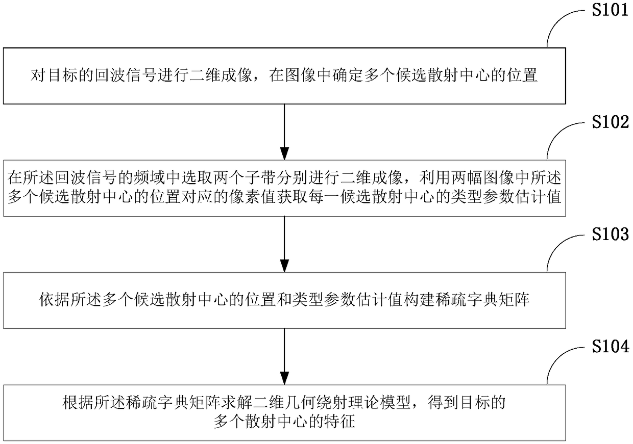
[0030] figure 1 is a schematic diagram of the main steps of the method for extracting the features of the target scattering center according to the embodiment of the present invention.

[0031] Such as figure 1 As shown, the present invention is an embodiment of a method for extracting target scattering center features that can specifically...


PUM


Abstract

The invention relates to a method and device of extracting the characteristics of a target scattering center, and the implementation of the method of extracting the characteristics of target scattering center comprises the following steps: two-dimensional imaging of the target echo signal, and determining the location of a plurality of candidate scattering centers in the image; selecting two sub-bands in the frequency domain of the echo signal for two-dimensional imaging, and estimating the type parameters of each candidate scattering center by using the pixel values corresponding to the positions of the multiple candidate scattering centers in the two images; constructing a sparse dictionary matrix according to the position and type parameter estimate of the multiple candidate scatteringcenters; solving the two-dimensional geometric diffraction model based on the sparse dictionary matrix, and obtaining the characteristics of multiple scattering centers of the target. The implementation of extracting the characteristics of target scattering center can accurately extract the scattering center characteristics of the target by using two-dimensional geometric diffraction model.

Description

technical field [0001] The invention relates to the technical field of radar signal processing, in particular to a method and device for extracting features of a target scattering center. Background technique [0002] The GTD (Geometric Theory of Diffraction) model is a mathematical model that describes the mechanism of high-frequency electromagnetic scattering. Its parameter estimation methods can be divided into two categories: the first category is parameter estimation based on physical models. Directly estimate the parameters of the prototype of the GTD model, among which the more representative ones include the maximum likelihood method, the sparse solution method, etc.; the second type is the parameter estimation based on the mathematical model, which approximates the GTD model echo into a band attenuation Various classical spectral estimation methods such as ESPRIT, MUSIC, RELAX, etc. can be applied to the solution of such problems. Since the second type of method has...

Claims


Application Information

Patent Timeline
IPC IPC(8): G01S7/41
CPCG01S7/41
Inventor 邢笑宇霍超颖满良冯雪健
Owner BEIJING INST OF ENVIRONMENTAL FEATURES
Learn More