Accounting book punching device

A punching device and ledger technology, which is applied in binding and other directions, can solve the problems of easily damaged documents, and achieve the effects of reducing friction, simple structure, and easy use

Active Publication Date: 2020-09-01
FUYANG NORMAL UNIVERSITY
View PDF9 Cites 0 Cited by
  • Summary
  • Abstract
  • Description
  • Claims
  • Application Information

AI Technical Summary

Problems solved by technology

[0003] What the present invention aims to overcome is the problem that the traditional paper file punching device is easy to damage the upper layer of files due to the rotation of the drill bit during the drilling process. The purpose is to provide a punching device for accounting books

Method used


Image

  • Accounting book punching device
  • Accounting book punching device
  • Accounting book punching device

Examples


Embodiment 1

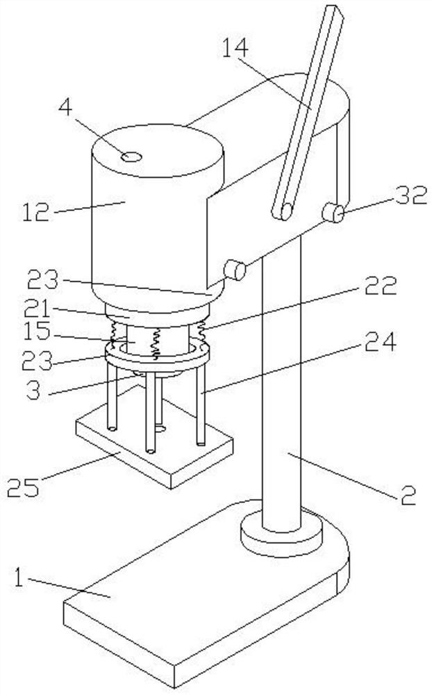
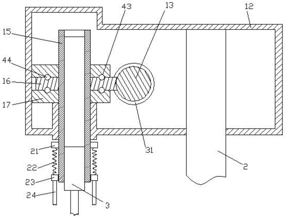
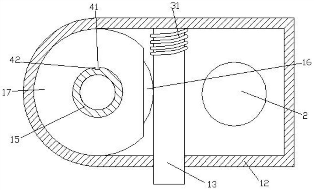
[0022] combine figure 1 , figure 2 , image 3 Shown; A kind of account book punching device for accounting, including base 1, column 2, drilling machine 3, control switch 4, column 2 is vertically installed on the top of base 1, column 2 upper end is equipped with spindle box 12, the inside of spindle box 12 A worm 13 is installed, one end of the worm 13 is connected to the lower pressure rod 14, the lower pressure rod 14 is located outside the headstock 12, the end of the headstock 12 is equipped with a main shaft 15, the main shaft 15 is perpendicular to the base 1 surface, and the outside of the main shaft 15 corresponds to the position of the worm 13 Surrounded by a gear ring 16, a clamping plate 17 is arranged inside the headstock 12, the main shaft 15 passes through the clamping plate 17, the gear ring 16 is located between two sets of clamping plates 17, the interior of the main shaft 15 is hollow, and the drilling machine 3 is fixedly installed on the main shaft 15 ...

Embodiment 2

[0029] combine figure 1 , figure 2 , image 3 Shown; A kind of account book punching device for accounting, including base 1, column 2, drilling machine 3, control switch 4, column 2 is vertically installed on the top of base 1, column 2 upper end is equipped with spindle box 12, the inside of spindle box 12 A worm 13 is installed, one end of the worm 13 is connected to the lower pressure rod 14, the lower pressure rod 14 is located outside the headstock 12, the end of the headstock 12 is equipped with a main shaft 15, the main shaft 15 is perpendicular to the base 1 surface, and the outside of the main shaft 15 corresponds to the position of the worm 13 Surrounded by a gear ring 16, a clamping plate 17 is arranged inside the headstock 12, the main shaft 15 passes through the clamping plate 17, the gear ring 16 is located between two sets of clamping plates 17, the interior of the main shaft 15 is hollow, and the drilling machine 3 is fixedly installed on the main shaft 15 ...


PUM


Abstract

The invention discloses a punching device for an accounting book. The punching device comprises a base, a stand column, a drilling machine and a control switch, wherein the stand column is perpendicularly mounted on the upper part of the base; the upper end of the stand column is equipped with a spindle box; a worm is mounted inside the spindle box; one end side of the worm is connected with a pressing rod; the end side of the spindle box is equipped with a spindle; the position, which corresponds to the worm, outside the spindle is equipped with a gear ring in a surrounding mode; a blocking plate is arranged inside the spindle box; the gear ring is positioned between groups of blocking plates; the spindle is internally hollow; the drilling machine is fixedly mounted at the lower end inside the spindle; a limiting ring is arranged on the outer surface of the lower part of the spindle; the limiting ring is positioned on the outer part of the spindle box; the lower part of the limiting ring is equipped with four groups of extrusion springs at equal angles; the lower ends of the extrusion springs are connected with slide rings; the lower ends of the slide rings are equipped with fourgroups of ejector rods at equal angles; the bottom ends of the ejector rods are connected with a base plate; and the position, which corresponds to the rotary shaft of the drilling machine, of the middle part of the base plate is provided with a hole slot.

Description

technical field [0001] The invention relates to the field of accounting supplies, in particular to a device for punching holes in accounting books. Background technique [0002] For accounting personnel such as company accountants, they have to contact a large number of bills and bills every day; regularly and quantitatively sorting out various bills and binding them into books plays an important role in checking accounts and post-audit checks; so a certain number of bills are bound Booklets with a standard thickness or number of sheets have become part of the daily work of accountants and other accounting personnel. In order to liberate labor and increase efficiency, related binding equipment has also emerged in an endless stream. When binding paper documents, relatively thin documents can be used Stapler is used for binding, and thicker paper documents are usually drilled with a punching device and then bound with pins or threaded. However, the traditional paper file punch...

Claims


Application Information

Patent Timeline
Patent Type & Authority Patents(China)
IPC IPC(8): B42B5/02
CPCB42B5/02
Inventor 魏清
Owner FUYANG NORMAL UNIVERSITY
Why Eureka
Try Eureka