Plastic pipe welding device
A welding device and plastic pipe technology, which is applied in the field of plastic pipes, can solve the problems of demanding operation and achieve the effects of reducing contact area, improving stability, and preventing offset
- Summary
- Abstract
- Description
- Claims
- Application Information
AI Technical Summary
Problems solved by technology
Method used
Image
Examples
Embodiment 1
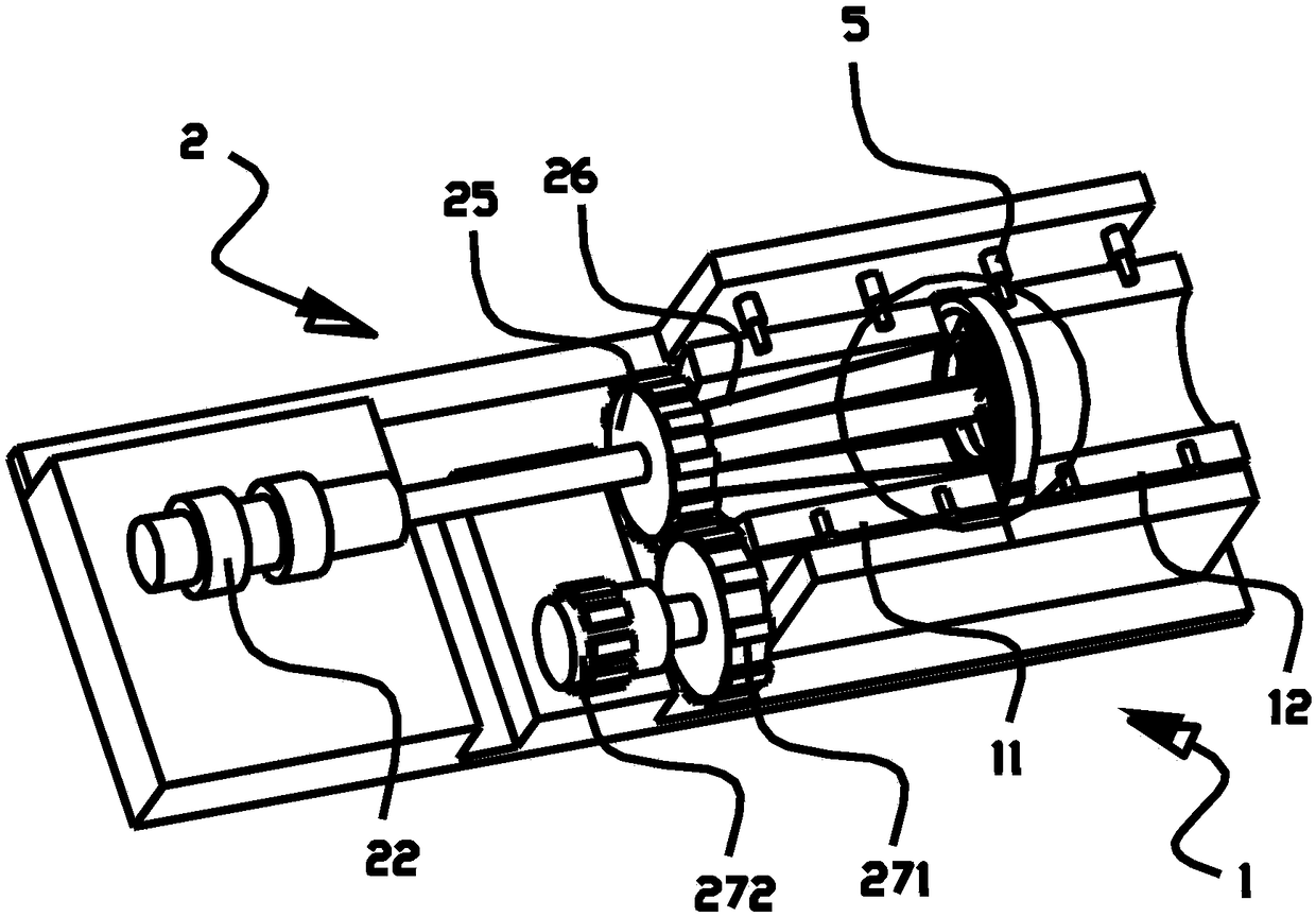
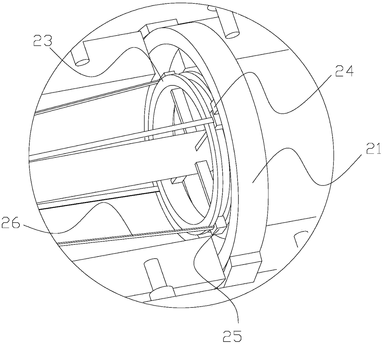
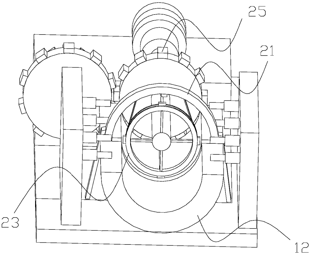
[0038] Such as figure 1 , 2As shown, this embodiment discloses a plastic pipe welding device, which includes a welding station 1 and a hot-melt device. After the two plastic pipes to be welded are combined on the welding station 1, the two plastic pipes to be welded Welding at the interface. The hot-melt device includes an external fixed guide ring 21, a telescopic device 22, a built-in fixed guide ring 23, an external heating rod 24, and a built-in heating rod 25. The built-in fixed guide ring 23 is connected with the telescopic end of the telescopic device 22, and the telescopic device 22 The elongation movement of the telescopic end can drive the built-in fixed guide ring 23 to move from the end of the inner cavity of one of the plastic pipes to be welded to the inner cavity at the interface and ensure that the built-in fixed guide ring 23 is concentric with the interface.
[0039] The built-in heating rod 25 is slidingly matched with the built-in fixed guide ring 23, and...
Embodiment 2
[0044] Such as figure 1 , 2 As shown, this embodiment discloses a plastic pipe welding device, which includes a welding station 1 and a hot-melt device. After the two plastic pipes to be welded are combined on the welding station 1, the two plastic pipes to be welded Welding at the interface. The hot-melt device includes an external fixed guide ring 21, a telescopic device 22, a built-in fixed guide ring 23, an external heating rod 24, and a built-in heating rod 25. The built-in fixed guide ring 23 is connected with the telescopic end of the telescopic device 22, and the telescopic device 22 The elongation movement of the telescopic end can drive the built-in fixed guide ring 23 to move from the end of the inner cavity of one of the plastic pipes to be welded to the inner cavity at the interface and ensure that the built-in fixed guide ring 23 is concentric with the interface.
[0045] The built-in heating rod 25 is slidingly matched with the built-in fixed guide ring 23, an...
Embodiment 3
[0050] Such as figure 1 , 2 As shown, this embodiment discloses a plastic pipe welding device, which includes a welding station 1 and a hot-melt device. After the two plastic pipes to be welded are combined on the welding station 1, the two plastic pipes to be welded Welding at the interface. The hot-melt device includes an external fixed guide ring 21, a telescopic device 22, a built-in fixed guide ring 23, an external heating rod 24, and a built-in heating rod 25. The built-in fixed guide ring 23 is connected with the telescopic end of the telescopic device 22, and the telescopic device 22 The elongation movement of the telescopic end can drive the built-in fixed guide ring 23 to move from the end of the inner cavity of one of the plastic pipes to be welded to the inner cavity at the interface and ensure that the built-in fixed guide ring 23 is concentric with the interface.
[0051] The built-in heating rod 25 is slidingly matched with the built-in fixed guide ring 23, an...
PUM
 Abstract
Description
Claims
Application Information
 - R&D Engineer
- R&D Manager
- IP Professional
- Industry Leading Data Capabilities
- Powerful AI technology
- Patent DNA Extraction
Browse by: Latest US Patents, China's latest patents, Technical Efficacy Thesaurus, Application Domain, Technology Topic, Popular Technical Reports.
© 2024 PatSnap. All rights reserved.Legal|Privacy policy|Modern Slavery Act Transparency Statement|Sitemap|About US| Contact US: help@patsnap.com


