
Fire-fighting water system for super-high-rise building construction stage and construction method

A technology of building construction and construction method, applied in fire rescue and other directions, can solve the problems of pipeline and electromechanical arrangement and construction impact, high construction cost, and difficulty in dismantling, so as to reduce construction tasks and demolition tasks, and reduce construction workload. , the effect of high construction efficiency

Active Publication Date: 2019-03-08
CHINA CONSTR THIRD ENG BUREAU GRP CO LTD +1
View PDF8 Cites 3 Cited by
  • Summary
  • Abstract
  • Description
  • Claims
  • Application Information

AI Technical Summary

Problems solved by technology

[0005] The technical problem to be solved is: the existing temporary fire water system is a purely temporary fire water system, which is relatively independent from the formal fire water system of the building, and will be dismantled in the end, which is difficult and requires a lot of work. There are many closures, which is time-consuming and labor-intensive; the construction cost is high, and it occupies a large space, which will have a great impact on the layout and construction of subsequent pipelines and electromechanical equipment

Method used


Image

  • Fire-fighting water system for super-high-rise building construction stage and construction method
  • Fire-fighting water system for super-high-rise building construction stage and construction method
  • Fire-fighting water system for super-high-rise building construction stage and construction method

Examples


Embodiment Construction

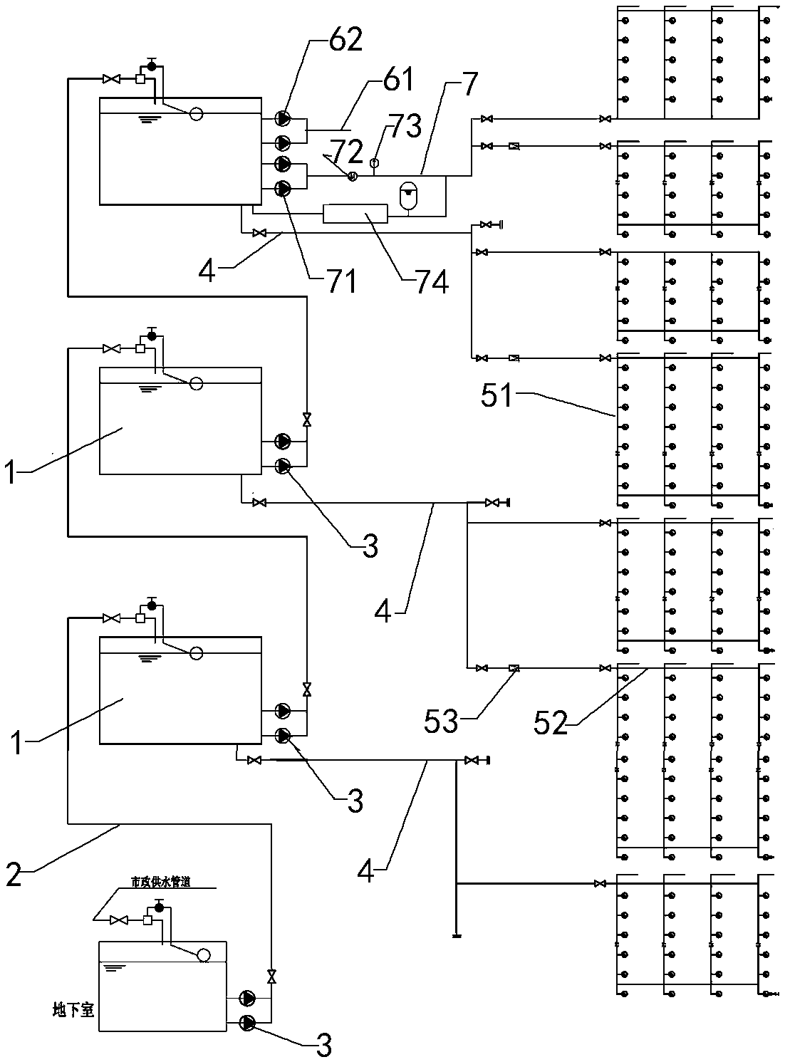
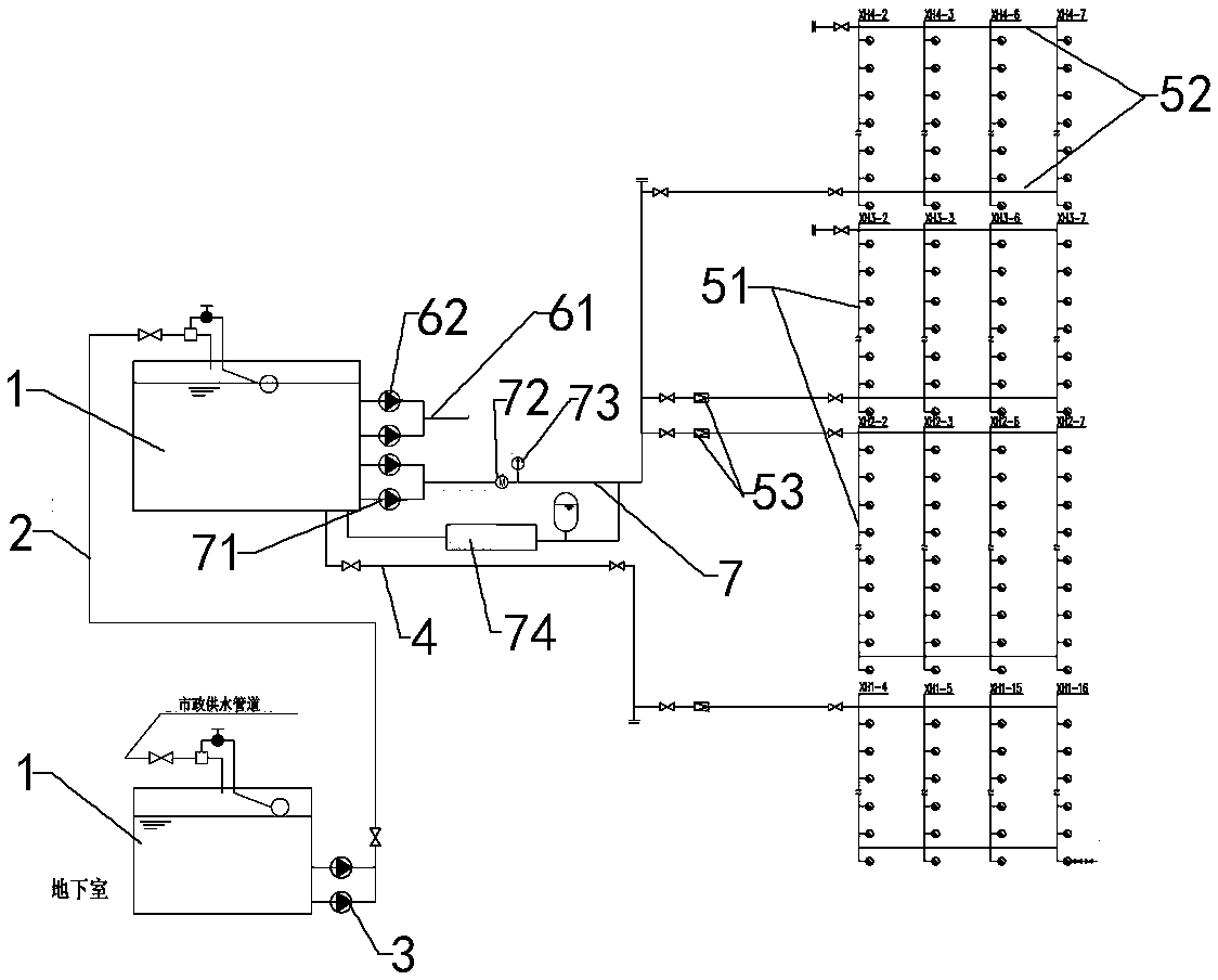
[0042] Such as figure 1 Shown, the present invention is used for the fire-fighting water system of super high-rise building construction phase and comprises the fire-fighting transfer water tank 1 that building is used formally, temporary fire-fighting water supply pipe network, the temporary water supply that connects fire-fighting transfer water tank 1 and temporary fire-fighting water supply pipe network Pipeline 4, and a temporary fire hydrant connected to the outlet of the temporary fire water supply network.

[0043]A fire transfer water tank 1 is installed every 100-140m in a super high-rise building. The transfer pipe 2 is connected with the fire protection transfer pipe 2. The transfer pipe 2 is a steel pipe with a nominal diameter of not less than 250mm. The transfer pipe 2 is provided with a temporary transfer pump 3. The lift of the temporary transfer pump 3 is higher than that of the official fire protection transfer pump 9. Each fire-fighting transfer water tank...


PUM


Abstract

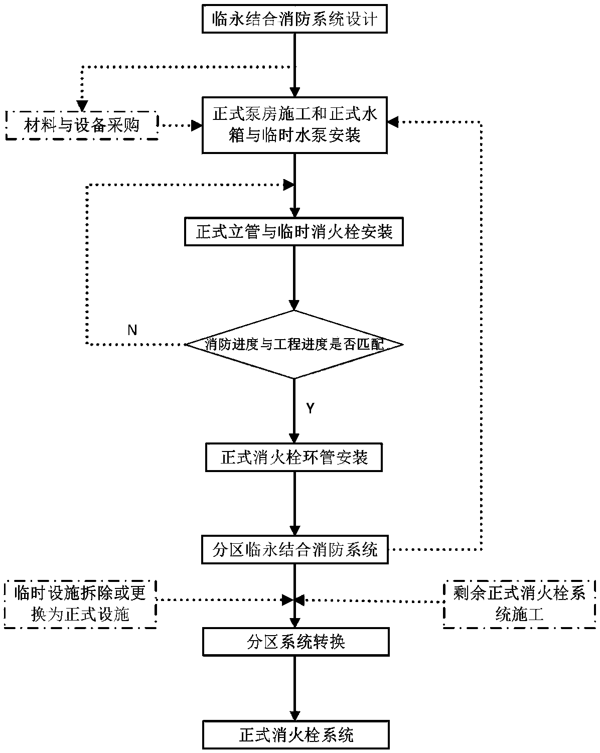
The invention relates to the technical field of fire extinguishing systems in a building construction stage, and discloses a fire-fighting water system for a super-high-rise building construction stage and a construction method. The system comprises formal fire-fighting intermediate water tanks, a temporary fire-fighting water supply pipe network, and a temporary fire hydrant connected with a water outlet of the temporary fire-fighting water supply pipe network; the upper and lower adjacent fire-fighting intermediate water tanks communicate through rotary conveying pipelines, and temporary rotary conveying pumps are arranged on the rotary conveying pipelines; each fire-fighting intermediate water tank communicates with the temporary fire-fighting water supply pipe network located between the fire-fighting intermediate water tank and the adjacent fire-fighting intermediate water tank in the lower part through a temporary water supply pipeline; and a water outlet of the fire-fighting intermediate water tank located at the uppermost layer in the construction process communicates with a construction water pipeline and a formal fire-fighting water supply pipeline, and the temporary fire-fighting water supply pipe network comprises first-batch fire-fighting water supply vertical pipes and fire-fighting water supply ring pipes, wherein the first-batch fire-fighting water supply vertical pipes and the fire-fighting water supply ring pipes are used for formal fire fighting. According to the system, a part of the formal fire fighting water system is used, so that the disassembly workload is small, and the construction cost is low.

Description

technical field [0001] The invention relates to the technical field of fire-fighting systems in the building construction stage, in particular to a fire-fighting water system used in the construction stage of a super high-rise building and a construction method thereof. Background technique [0002] During the construction of super high-rise buildings, due to the exposure of construction materials and the splashing of electric welding sparks, there are great safety hazards. It is necessary to install a fire protection water system in time. However, during the construction process, the formal fire protection water system of the building has not yet been installed. Completed, it cannot be officially put into use, so a temporary fire water system needs to be set up. [0003] The temporary fire water system used in the current construction process is a purely temporary fire water system, which is relatively independent of the formal fire water system of the building. After the c...

Claims


Application Information

Patent Timeline
Patent Type & Authority Applications(China)
IPC IPC(8): A62C31/00A62C35/20
CPCA62C31/00A62C35/20Y02A20/00
Inventor 许立山罗汾毅彭明祥曾运平马志鹏蒋凯张超刘庆海周航吴金龙卢松
Owner CHINA CONSTR THIRD ENG BUREAU GRP CO LTD
Learn More