Energy storage system monitoring method, device and system
An energy storage system and monitoring data technology, which is applied in the electric power field, can solve the problems of large amount of communication data, multiple transmission resources, and consumption, and achieve the effect of saving transmission resources and reducing the amount of communication data
- Summary
- Abstract
- Description
- Claims
- Application Information
AI Technical Summary
Problems solved by technology
Method used
Image

Examples
Embodiment 1
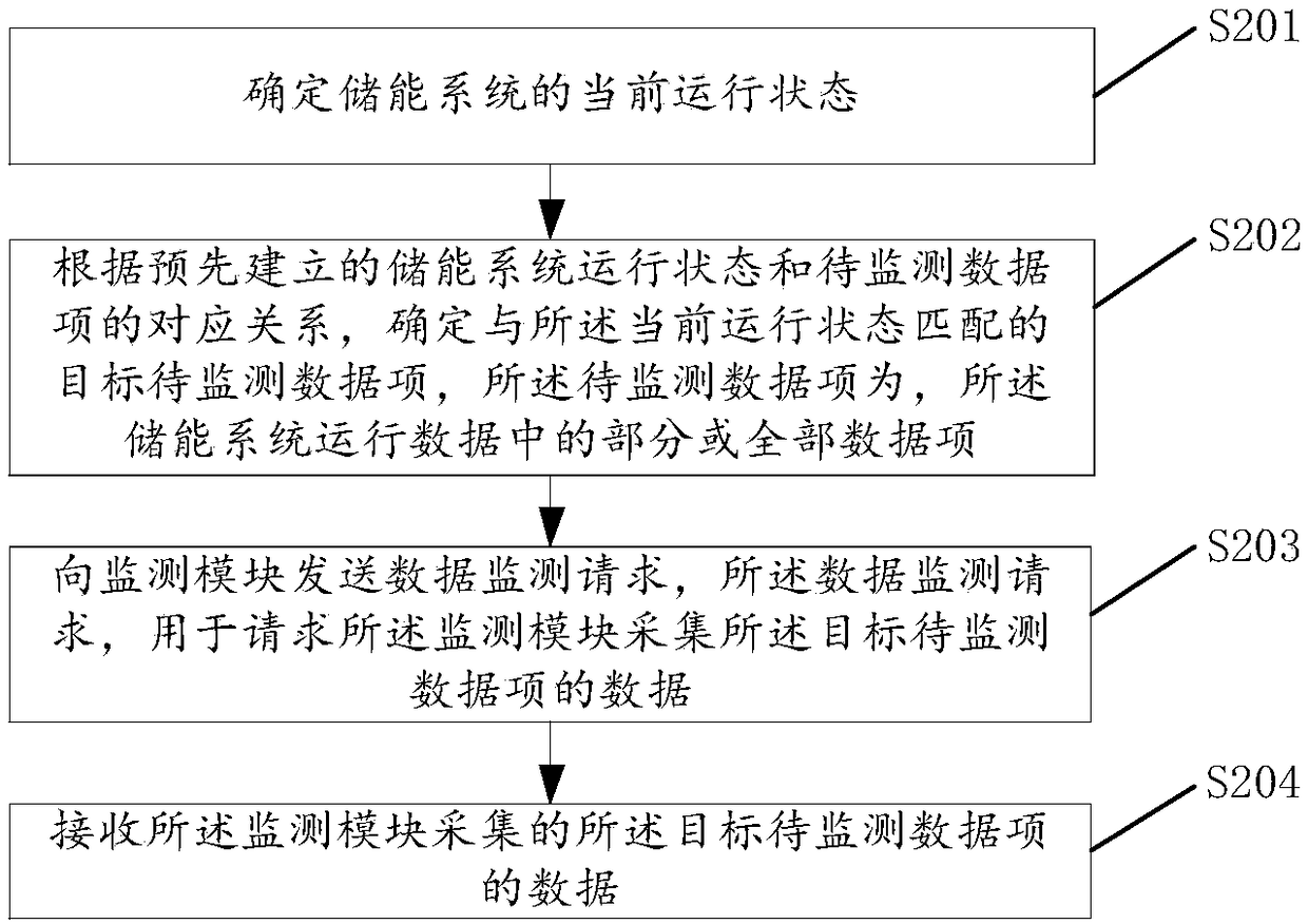
[0047] Please refer to figure 2 , figure 2 It shows a schematic flow chart of an energy storage system monitoring method provided in Embodiment 1 of the present application.
[0048] In order to facilitate understanding, the following first combine Figure 3A to Figure 3C The executor who implements the energy storage system monitoring method provided in Embodiment 1 of the present application will be described.
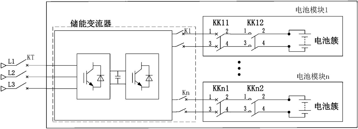
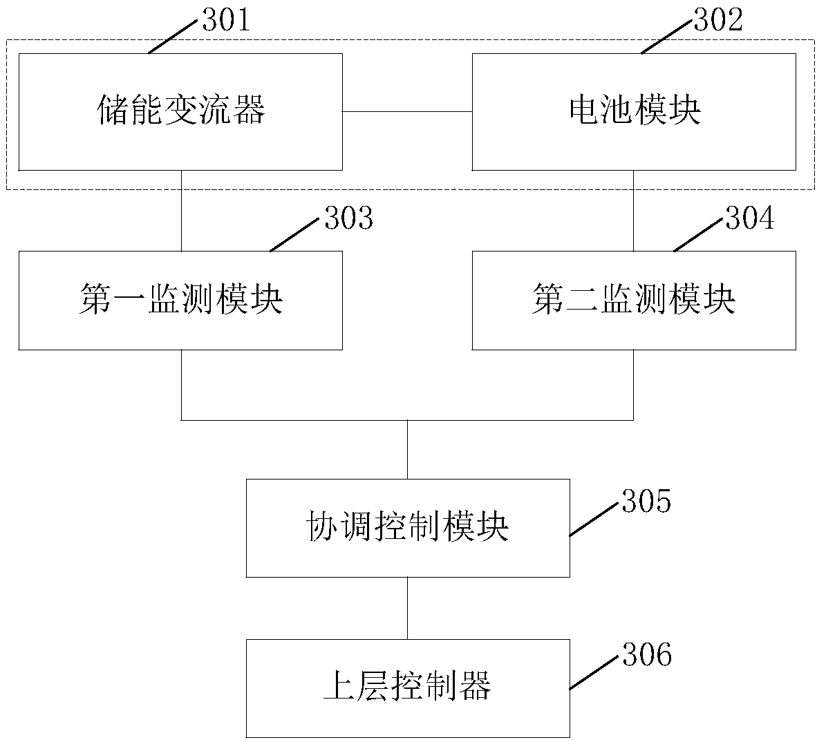
[0049] Such as Figure 3AAs shown, the coordination control module 305 controls the first monitoring module 303 and the second monitoring module 304 to monitor the operation data of the energy storage converter 301 and the battery module 302 respectively, and the first monitoring module 303 and the second monitoring module 304 will The data obtained by monitoring is uploaded to the coordination control module 305, and then uploaded to the upper controller 306 in the power grid by the coordination control module 305. exist Figure 3A In the application scenario...
Embodiment 2
[0149] Please refer to Figure 7 , Figure 7 It shows a schematic flow chart of an energy storage system monitoring method provided in Embodiment 2 of the present application. Such as Figure 7 As shown, the method may include:
[0150] S701. Receive a data monitoring request sent by the control module; the data monitoring request includes a target data item to be monitored; the target data item to be monitored is a data item to be monitored that matches the current operating state of the energy storage system; the The data items to be monitored are some or all of the data items in the operation data of the energy storage system;
[0151] Specifically, as described in Embodiment 1, the data items to be monitored that match the current operating state of the energy storage system can be determined according to the previously established correspondence between the operating state of the energy storage system and the data items to be monitored.
[0152] Wherein, the operating...
Embodiment 3
[0181] Based on the above-mentioned embodiment 1 and embodiment 2, please refer to Figure 8 , Figure 8 It shows a schematic flow chart of an energy storage system monitoring method provided in Embodiment 3 of the present application, as shown in Figure 8 As shown, the method can include:
[0182] S801. Initialize the monitoring module;
[0183] The specific implementation content of step S801 corresponds to the above-mentioned Figure 4 A description of what is shown, combined with Figure 3A It can be known that step S801 may specifically include: initializing the first monitoring module 303 and the second monitoring module 304 when accessing the coordination control module 305 for the first time. Wherein, the first monitoring module 303 is used for monitoring the operation data of the energy storage converter 301, and the second monitoring module 304 is used for monitoring the operation data of the battery module 302. For a more detailed description of the initializa...
PUM
 Abstract
Description
Claims
Application Information
 - Generate Ideas
- Intellectual Property
- Life Sciences
- Materials
- Tech Scout
- Unparalleled Data Quality
- Higher Quality Content
- 60% Fewer Hallucinations
Browse by: Latest US Patents, China's latest patents, Technical Efficacy Thesaurus, Application Domain, Technology Topic, Popular Technical Reports.
© 2025 PatSnap. All rights reserved.Legal|Privacy policy|Modern Slavery Act Transparency Statement|Sitemap|About US| Contact US: help@patsnap.com