The structure of the feeding part of the steel pipe flaw detection

A technology of feeding part and steel pipe, which is applied in the direction of material analysis by electromagnetic means, material analysis, and material analysis by using sound wave/ultrasonic wave/infrasonic wave, etc. It can solve the problems of probe vibration, warping, signal amplitude change, etc., and achieve Good straightening effect, simple structure, and the effect of improving the effect of flaw detection

Active Publication Date: 2021-10-26
宝武特冶航研科技有限公司
View PDF14 Cites 0 Cited by
  • Summary
  • Abstract
  • Description
  • Claims
  • Application Information

AI Technical Summary

Problems solved by technology

In the actual automatic flaw detection process, because the steel pipe is in the transmission process of detection, the probe of the existing ultrasonic automatic flaw detection device is usually directly fixed on the probe bracket, and the probe bracket is fixedly connected with the flaw detection water tank, because there are many types of steel pipes, The fixed setting of the probe cannot meet the flaw detection requirements of various types of steel pipes
At the same time, in the process of steel pipe flaw detection, when the defect position of the steel pipe passes through, it is easy to touch the probe and cause the probe to vibrate and warp, resulting in a change in the amplitude of the defect signal. If it cannot be adjusted in time, it will also affect the reliability and accuracy of flaw detection. sex

Method used


Image

  • The structure of the feeding part of the steel pipe flaw detection
  • The structure of the feeding part of the steel pipe flaw detection
  • The structure of the feeding part of the steel pipe flaw detection

Examples


Embodiment Construction

[0049] The present invention will be further described in detail below in combination with a steel pipe flaw detection system adopting the structure of the present invention and the accompanying drawings.

[0050] During specific implementation: if Figure 1 to Figure 10 shown.

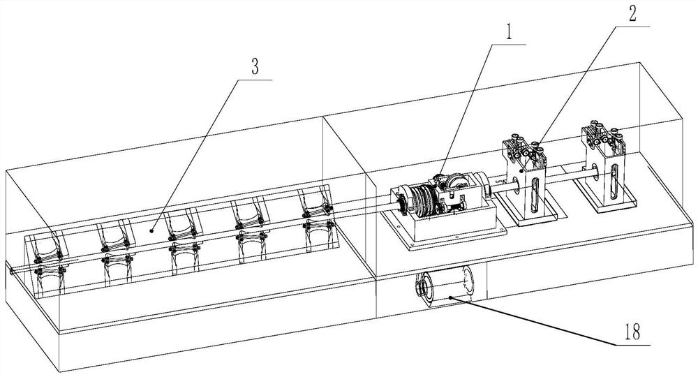
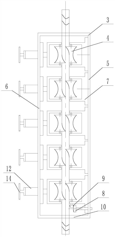
[0051] A steel pipe flaw detection system, including a base plate, on which a steel pipe transmission device 1 for driving the steel pipe to move along the axis direction and a steel pipe flaw detection device 2 arranged on the steel pipe movement path are arranged on the bottom plate, and a steel pipe feeding straightening device arranged on the bottom plate Device 3, steel pipe feeding and straightening device 3 is arranged at the feeding end of the steel pipe transmission device and is used for straightening the steel pipe.

[0052] In this way, the steel pipe is straightened first and then the material is fed for flaw detection, which can better avoid the influence of the straightness or surface ...


PUM


Abstract

The invention discloses a steel pipe flaw detection feeding part structure, comprising a steel pipe transmission device for driving the steel pipe to move along the axis direction and a steel pipe feeding straightening device arranged at the feeding end of the steel pipe transmission device; The straightening device includes straightening rollers arranged in pairs. The circumferential surface of the straightening rollers is a concave arc in the middle. Two straightening rollers in each pair of straightening rollers are arranged on the left and right sides of the steel pipe movement path, and two The axis lines of the straightening rollers are dislocated and tilted up and down along the moving direction of the steel pipe, so that the two straightening rollers form two symmetrical helical contact with the surface of the steel pipe respectively. The invention can realize the straightening of the steel pipe during flaw detection and improve the flaw detection effect, and has the advantages of simple structure and good straightening effect.

Description

technical field [0001] The invention relates to a steel pipe flaw detection device; in particular, it relates to a steel pipe flaw detection feeding part structure. Background technique [0002] Steel pipe is an important steel material widely used. Due to various factors in the production process of steel pipe, defects such as longitudinal cracks, transverse cracks, folding, and delamination often exist on the steel pipe wall. If the steel pipe is defective, it will break during use and cause accidents, and even cause serious consequences, which may cause major economic losses or even casualties. For this reason, steel pipes for important purposes require complete non-destructive testing equipment to conduct online flaw detection on steel pipes. To ensure the quality of steel pipes leaving the factory, the existing flaw detection methods mainly include ultrasonic flaw detection and eddy current flaw detection inspection methods. The existing steel pipe flaw detection line ...

Claims


Application Information

Patent Timeline
Patent Type & Authority Patents(China)
IPC IPC(8): G01N1/28G01N29/27G01N29/22G01N27/90
CPCG01N1/286G01N27/9006G01N27/9093G01N29/22G01N29/223G01N29/27G01N2291/0234G01N2291/0289
Inventor 吴建军董宝渝赵伟
Owner 宝武特冶航研科技有限公司
Why Eureka
Try Eureka