Tank valve

A storage tank and valve seat technology, which is applied in the direction of lifting valves, valve details, control valves, etc., can solve the problems of complex shape of parts and high cost of storage tank valves, and achieve the effects of improved elasticity, low cost, and cost reduction

Inactive Publication Date: 2019-03-01
DAIMLER AG
View PDF9 Cites 0 Cited by
  • Summary
  • Abstract
  • Description
  • Claims
  • Application Information

AI Technical Summary

Problems solved by technology

Another disadvantage is the high cost of this type of tank valve, because such a tank valve requires a very large number of different parts inside, some of which have extremely complex shapes

Method used


Image

  • Tank valve
  • Tank valve
  • Tank valve

Examples


Embodiment Construction

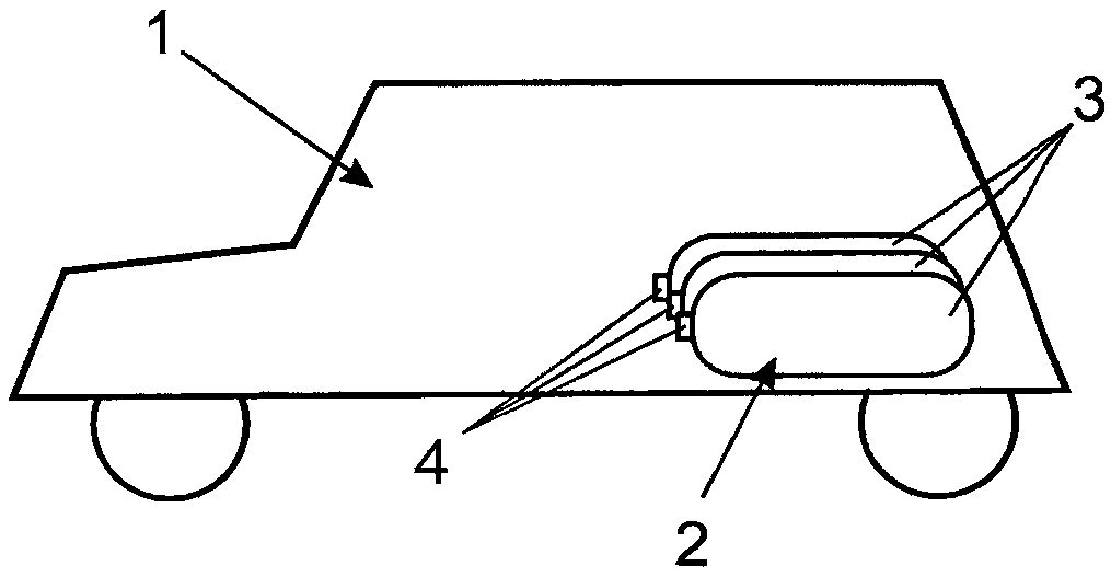
[0024] figure 1The vehicle 1 is shown purely by way of example. The vehicle is powered by a gaseous fuel, such as compressed natural gas or compressed hydrogen. For this purpose, the fuel can be converted into power for the drive in the internal combustion engine or, especially when hydrogen is used, preferably also in the fuel cell system. In order to store compressed gas, there is a storage device designated as a whole with 2 in the vehicle 1 . The storage device consists of several individual compressed gas containers 3 each having a tank valve 4 . The storage tank valve 4 is also called On-Tank-Valve, or OTV for short. Therein, the individual compressed gas containers 3 together with their storage tank valves 4 can be connected to one another, for example in a manner known from the aforementioned prior art, via common pipes in order to be able to use the gas from the storage device 2 in the vehicle. The nominal pressure of such a compressed gas container 3 with storage...


PUM


Abstract

The invention relates to a tank valve (4) for mounting on a pressurized-gas container (3), having a main body (5), having multiple functional subassemblies for the refilling of the pressurized-gas accumulator (3), for the removal of gas from the pressurized-gas accumulator (3) and for the implementation of safety and operating functions, wherein one of the functional subassemblies is formed as anextraction valve (6), and wherein at least one of the other functional subassemblies is formed as a check valve (14, 17). The tank valve according to the invention is characterized in that both the extraction valve (6) and the at least one check valve (14, 17) have in each case one valve seat carrier (22) with a valve seat (21) and one valve body (19), wherein that part of the valve seat carrier (22) which interacts with the valve body (19) has a sealing lip (23), which projects in an axial direction, as part of the valve seat (21).

Description

technical field [0001] The invention relates to a tank valve of the type defined in detail in the preamble of claim 1 . The invention also relates to the use of such tank valves. Background technique [0002] Tank valves that can be mounted on compressed gas containers are known from the general prior art. The English name of such a storage tank valve is On-Tank-Valve, or OTV for short. In this case, the tank valve is a structure comprising a base body which has the so-called functional subgroups required for the function of the tank valve. Such functional subgroups may include, for example, extraction valves, non-return valves, safety valves, (manual) shut-off valves, filters, gas connections for filling and / or extraction or the like. [0003] Regarding this kind of storage tank valve, JP 2009-168165 A should be exemplarily referred to, which discloses a storage tank valve under the name of high pressure valve. Other valves are known, for example, from US 2009 / 0146094 A...

Claims


Application Information

Patent Timeline
IPC IPC(8): F16K1/30F17C13/04
CPCF16K1/305F17C13/04F17C2205/0335F17C2205/0385F17C2221/012F17C2223/0123F17C2223/036F17C2270/0168Y02E60/32F16K15/02F16K25/005
Inventor S·艾伯特F·高尔P·豪斯曼A·罗纳帝R·圣图利
Owner DAIMLER AG
Why Eureka
Try Eureka