Integrated foldable foundation-free concrete mixing plant
A foldable, concrete technology, applied in mixing plants, clay preparation devices, mixing operation control, etc., can solve the problems of tedious transportation and installation, affecting the time of putting into use of concrete mixing plants, etc., and achieves simple storage management and overall structural performance. Good, small footprint effect
- Summary
- Abstract
- Description
- Claims
- Application Information
AI Technical Summary
Problems solved by technology
Method used
Image
Examples
Embodiment 1
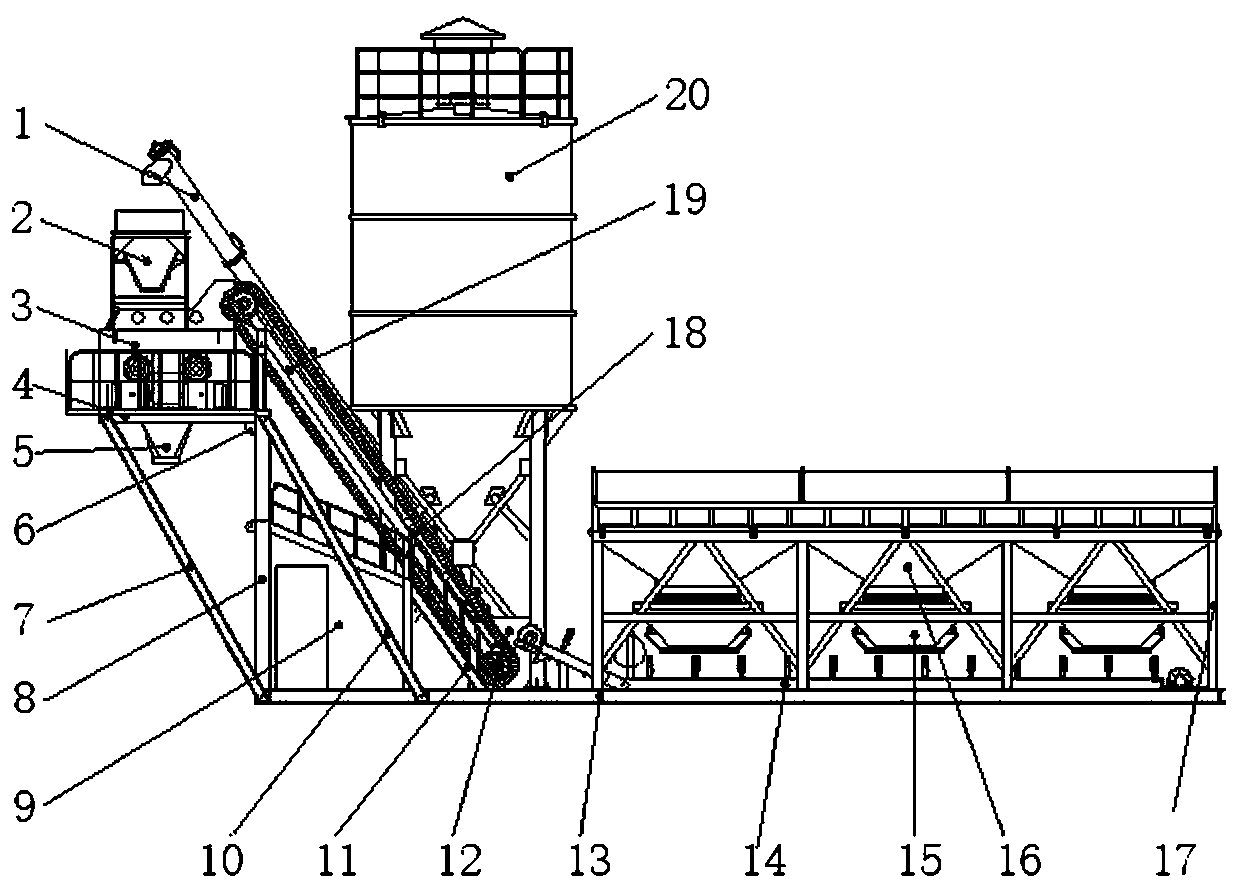
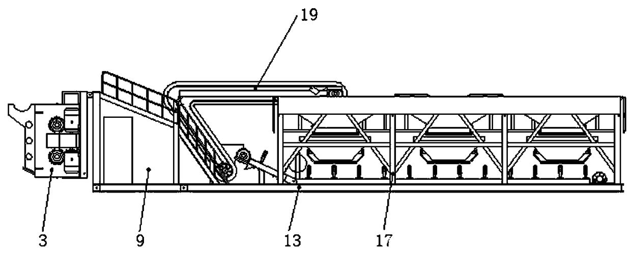
[0026] Embodiment 1: as Figure 1-2 As shown, the integrated foldable foundation-free concrete mixing plant includes a bottom frame 13 of frame structure, a batching machine bracket 17 for carrying the batching machine is arranged on one side of the bottom frame 13, and a horizontal conveyor is arranged at the bottom of the batching machine amount bracket 17 14. A main support frame 8 is provided on the other side of the bottom frame 13, an upper hinge point 6 is provided on the upper end of the main support frame 8 and a host platform 4 is hinged, a stirring host 3 is arranged on the host platform 4, and a stirring host 3 is provided on the host platform 4. A gathering hopper 5 is arranged at the discharge port; a belt conveyor 19 is arranged between the stirring host 3 and the discharge end of the horizontal conveyor 14, and the discharge end of the belt conveyor 19 communicates with the feed port of the stirring host 3 .
[0027] Further, the bottom frame of the silo is se...
Embodiment 2
[0037] Embodiment 2: as Figure 4-5 As shown, the integrated foldable foundation-free concrete mixing plant includes a bottom frame 13 of frame structure, and a batching machine bracket 17 for carrying a batching machine is arranged on one side of the bottom frame 13; a main support frame is arranged on the other side of the bottom frame 13 8. The upper hinge point 6 is set on the upper end of the main support frame 8 and the host platform 4 is hinged, the stirring host 3 is arranged on the host platform 4, and the gathering hopper 5 is arranged at the discharge port of the stirring host 3; A belt conveyor 19 is arranged between the discharge end of the horizontal conveyor 14, and the discharge end of the belt conveyor 19 communicates with the feed port of the mixing main engine 3; the lower end of the main support frame 8 is hinged with the rear end of the bottom frame 13, Between the front and rear ends of the host platform 4 and the bottom frame 13 are respectively connecte...
Embodiment 3
[0045] Embodiment 3: as Figure 4-6 As shown, a first hydraulic device 21 is installed between the host platform 4 and the main support frame 8 , and a second hydraulic device 23 is installed between the main support frame 8 and the bottom frame 13 . Through the setting of the hydraulic device, the use of the crane can be avoided, which is more convenient and faster.
[0046] During installation, the first step is to reset the belt conveyor 19 with a crane; the second step is to prop up the main support frame 8 to an upright state by the second hydraulic device 23; The main engine 3 props up and resets, and supports and fixes it with the first inclined support rod 7 and the second inclined support rod 24 after reset; the third step is to install the integrated metering scale 2, the bottom frame of the powder silo, the cement silo 20 and the screw conveyor 1 The installation is fixed, and the water tank can be placed at will according to the situation of the use site. It can b...
PUM
 Abstract
Description
Claims
Application Information
 - Generate Ideas
- Intellectual Property
- Life Sciences
- Materials
- Tech Scout
- Unparalleled Data Quality
- Higher Quality Content
- 60% Fewer Hallucinations
Browse by: Latest US Patents, China's latest patents, Technical Efficacy Thesaurus, Application Domain, Technology Topic, Popular Technical Reports.
© 2025 PatSnap. All rights reserved.Legal|Privacy policy|Modern Slavery Act Transparency Statement|Sitemap|About US| Contact US: help@patsnap.com


