
Small-size beam controllable patch antenna based on reconfigurable parasitic element

A technology of parasitic unit and patch antenna, which is applied in the field of wireless mobile communication and antenna research, can solve the problems of reconfigurable antenna tilt angle and small scanning range, large number of parasitic units, complex structure, etc., and achieve beam controllable performance , the effect of widening the working frequency band and simple circuit structure

Pending Publication Date: 2019-02-26
SOUTH CHINA UNIV OF TECH
View PDF0 Cites 18 Cited by
  • Summary
  • Abstract
  • Description
  • Claims
  • Application Information

AI Technical Summary

Problems solved by technology

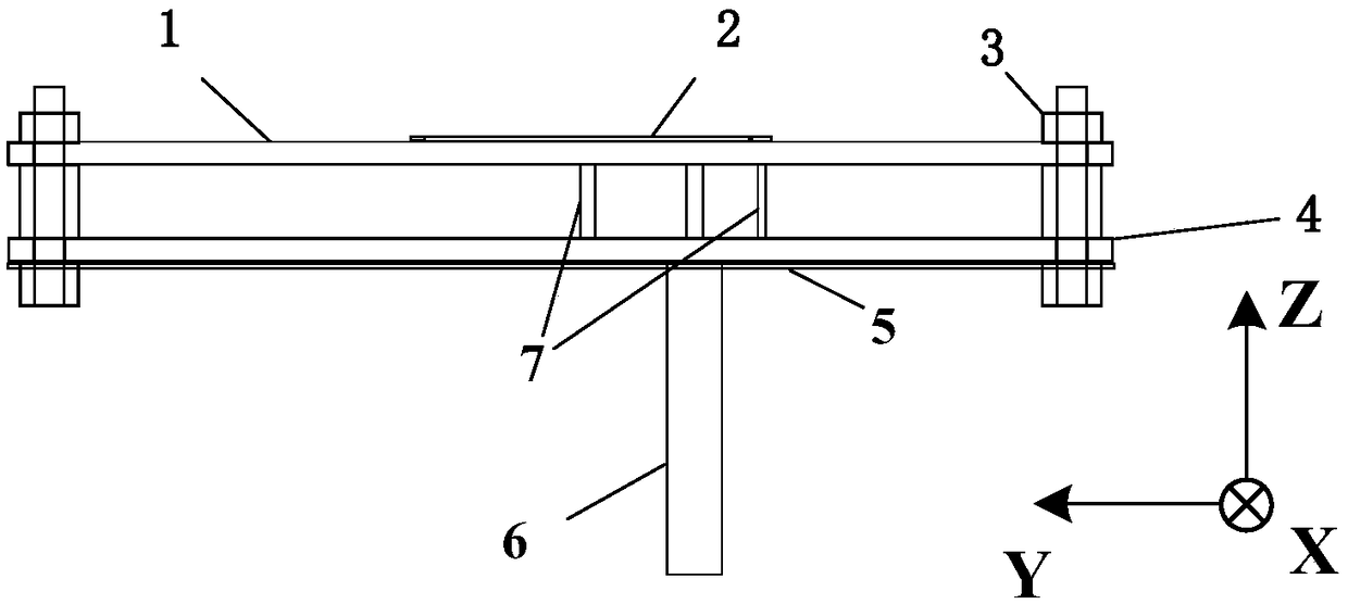
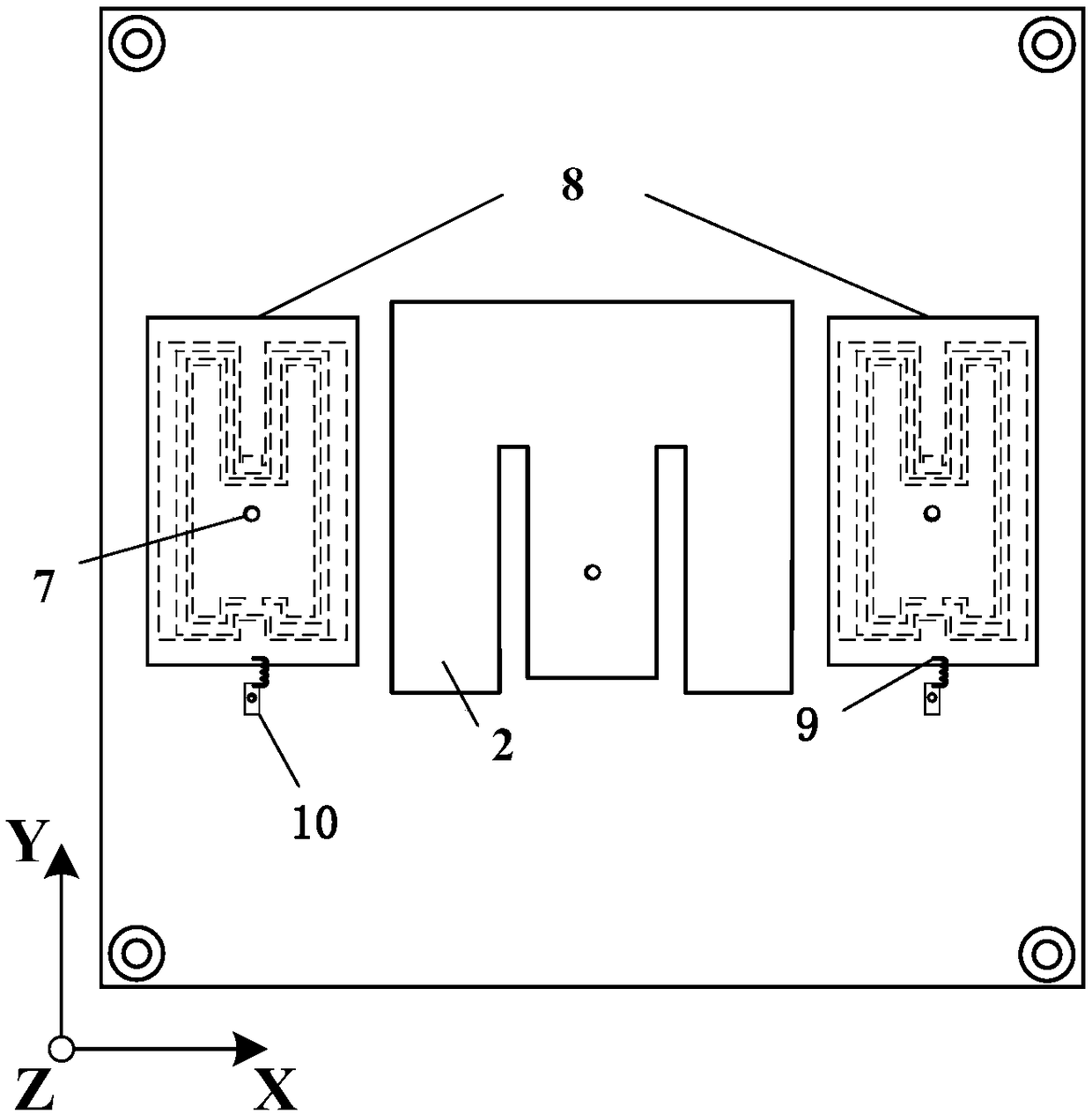
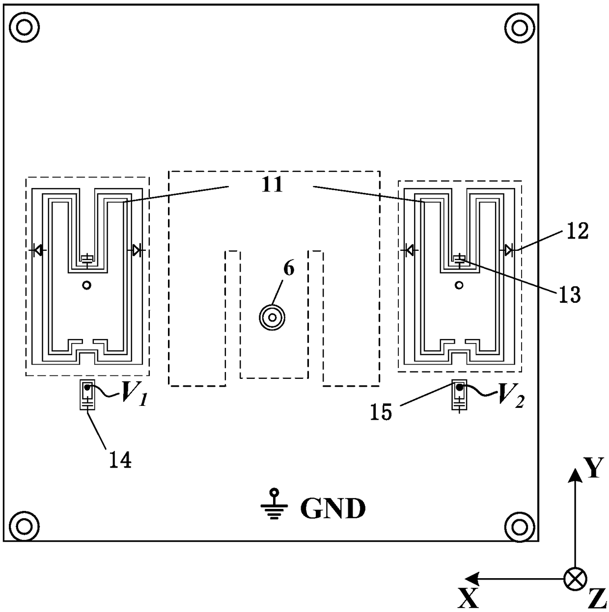
[0004] The present invention proposes a small patch antenna that uses CSRR (complementary split-ring resonator, complementary split-ring resonator) to control the beam, so as to solve the problems of traditional reconfigurable antennas with small tilt angle, small scanning range and narrow bandwidth. , the number of required parasitic units is too large, the structure is complex, the volume is large, etc.

Method used


Image

  • Small-size beam controllable patch antenna based on reconfigurable parasitic element
  • Small-size beam controllable patch antenna based on reconfigurable parasitic element
  • Small-size beam controllable patch antenna based on reconfigurable parasitic element

Examples


Embodiment Construction

[0033] The following will clearly and completely describe the technical solutions in the embodiments of the present invention with reference to the accompanying drawings in the embodiments of the present invention. Obviously, the described embodiments are only some, not all, embodiments of the present invention. Based on the embodiments of the present invention, all other embodiments obtained by persons of ordinary skill in the art without making creative efforts belong to the protection scope of the present invention.

[0034] For ease of description, the following and accompanying drawings will take the small beam steerable patch antenna as an example to illustrate the structure of the patch antenna provided by the embodiment of the present invention. It should be understood that the embodiment of the present invention is not limited to the small beam steerable patch antenna. patch antenna, but shall include all reconfigurable antennas having the features of the present inventi...


PUM


Abstract

The invention discloses a small-size beam controllable patch antenna based on a reconfigurable parasitic element, and the antenna comprises an E-shaped main radiation patch, a left parasitic patch anda right parasitic patch. Through employing a CSRR structure, the antenna reduces the electrical length of a parasitic patch, and facilitates the miniaturization of the parasitic patch. A PIN diode isadded to CSRR structure for providing different DC bias voltages, thereby enabling a single parasitic element to work at two states: a director and a reflector. The combination of different states ofthe left and right parasitic elements can enable the main lobe direction of a radiation beam of the antenna to be switched among 0 degree, -30 degree, and 30 degrees, thereby achieving the beam controllable performance of the antenna, and effectively enlarging the beam scanning range of the antenna. The antenna employs the coaxial feed E-shaped main radiation patch and introduces an air layer structure between two dielectric substrates, thereby effectively enlarging the work bandwidth of the antenna. The antenna is high in gain, is high in front-to-rear ratio, and is low in profile.

Description

technical field [0001] The invention relates to the antenna research field in the wireless mobile communication field, in particular to a small-beam steerable patch antenna based on a reconfigurable parasitic unit. Background technique [0002] The beam steerable antenna has the characteristic of beam reconfiguration in a fixed frequency band, which can expand the coverage of the transmitted signal and improve the scanning ability of the 5G MIMO antenna, which is a topic of great research significance. Therefore, in the past few years, researchers have proposed a large number of beam-steerable antennas. These antennas mainly use the following methods to achieve the characteristics of beam reconfiguration-new material technology, reconfigurable feed network, reconfigurable Structured electromagnetic metasurfaces, controlling parasitic elements and stimulating different working modes of radiators, etc. [0003] Among them, the use of new material technology can easily control...

Claims


Application Information

Patent Timeline
Patent Type & Authority Applications(China)
IPC IPC(8): H01Q9/04H01Q1/48H01Q1/50
CPCH01Q1/48H01Q1/50H01Q9/0407H01Q9/0442
Inventor 曹云飞刘楚钊章秀银韩欣洋
Owner SOUTH CHINA UNIV OF TECH
Learn More