Manufacturing method of separator for fuel cell

A technology for fuel cells and manufacturing methods, applied to fuel cell components, fuel cells, collectors/separators, etc., capable of solving problems such as changes in the shape and position of metal plates

Active Publication Date: 2021-06-15
TOYOTA JIDOSHA KK
View PDF6 Cites 0 Cited by
  • Summary
  • Abstract
  • Description
  • Claims
  • Application Information

AI Technical Summary

Problems solved by technology

In this case, since the metal plate is thermally extruded in a state of being sandwiched between conductive resin layers, the shape and position of the metal plate may vary

Method used


Image

  • Manufacturing method of separator for fuel cell
  • Manufacturing method of separator for fuel cell
  • Manufacturing method of separator for fuel cell

Examples


Embodiment Construction

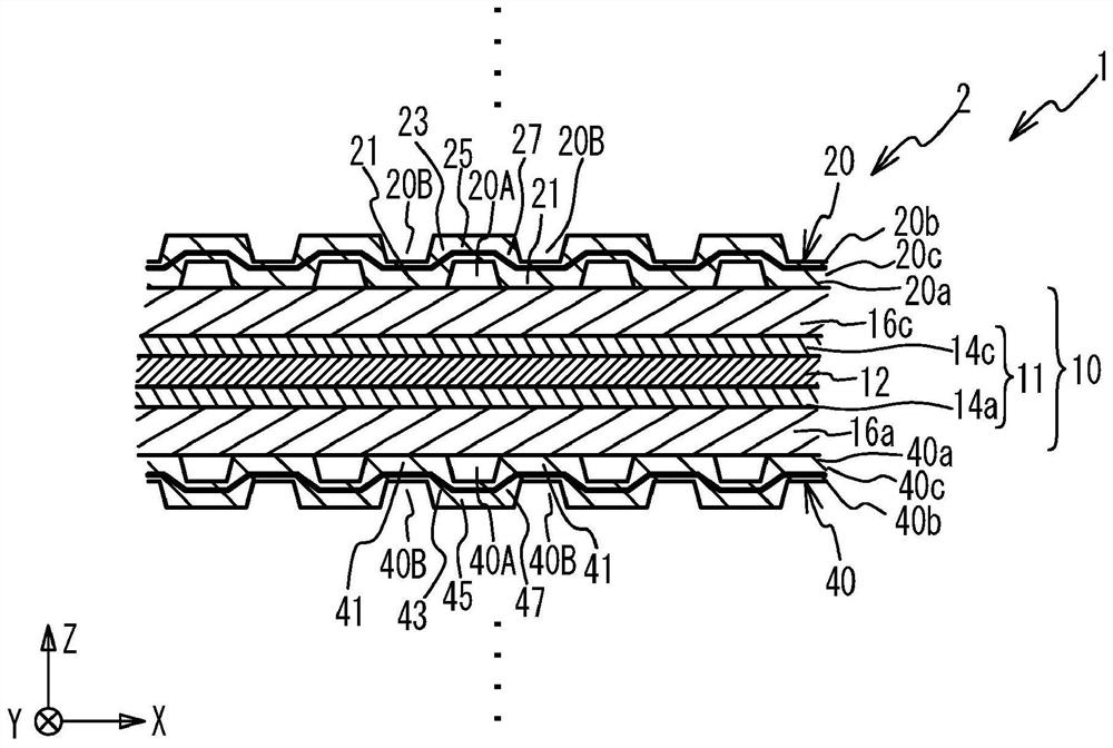
[0023] figure 1 is an exploded perspective view of a unit cell 2 of the fuel cell 1 . The fuel cell 1 is constructed by stacking unit cells 2 . figure 1 Only one single cell 2 is shown, and the other single cells are omitted. Single battery 2 in figure 1 Stacked with other single cells in the Z direction shown. The unit cells 2 have a substantially rectangular shape. The longitudinal direction and the short direction of the single battery 2 correspond to figure 1 The Y and X directions shown in .

[0024] The fuel cell 1 is a polymer electrolyte fuel cell that generates electricity using a fuel gas (such as hydrogen) and an oxidant gas (such as oxygen) as reaction gases. The single cell 2 comprises: a membrane electrode gas diffusion layer assembly 10 (hereinafter referred to as MEGA (membrane electrode gas diffusion layer assembly)); a support frame 18 supporting the MEGA 10; a cathode separator 20 and an anode separator 40 ( Hereinafter referred to as separator). MEG...


PUM


Abstract

A manufacturing method of a separator for a fuel cell includes: disposing a metal plate and first and second conductive resin sheets between first and second molds so that the first conductive resin sheet is disposed between the first mold and the metal plate , the second conductive resin sheet is arranged between the second mold and the metal plate, the metal plate having a plate shape is arranged between the first and second conductive resin sheets, the first mold includes: a first convex surface and a first concave surface the first side surface, the first side surface is connected between the first convex surface and the first concave surface, and the second mold includes: a second concave surface and a second convex surface, which respectively face the first convex surface and the first Concave surface; second side surface, the second side surface faces the first side surface and is connected between the second concave surface and the second convex surface; by using the first and the second mold hot extrusion on the metal plate and the first A flow channel is formed in a second conductive resin sheet on which a first protrusion protruding from the first side surface is formed.

Description

technical field [0001] The invention relates to a method of manufacturing a separator for a fuel cell. Background technique [0002] There is known a fuel cell comprising a pair of separators sandwiching a membrane electrode gas diffusion layer assembly. Such a separator is formed with a flow channel having a wave shape in cross-section. The reaction gas flows along the flow channel on the side of the membrane electrode gas diffusion layer assembly. The coolant flows on the side opposite to the flow channel. The membrane electrode gas diffusion layer assembly is sandwiched by the flow channels of the separator. In addition, there is known a separator including a metal plate and conductive resin layers provided on the corresponding surfaces of the metal plate. As for the flow channel, the metal plate and the conductive resin layer are formed to have waves in cross-section (for example, see Japanese Unexamined Patent Application Publication No. 2003-297383). [0003] As f...

Claims


Application Information

Patent Timeline
Patent Type & Authority Patents(China)
IPC IPC(8): H01M8/0258H01M8/0254
CPCH01M8/0254H01M8/0258H01M8/0206H01M8/0221H01M8/026Y02E60/50Y02P70/50
Inventor 田中秀明
Owner TOYOTA JIDOSHA KK
Why Eureka
Try Eureka