Back focal plane imaging device combined with low-temperature ultra-high vacuum scanning tunneling microscope

A technology for scanning tunnels and imaging devices, applied in the field of optical detection, can solve problems such as the inability to collect optical signals, and achieve the effects of facilitating positioning, preventing falling off, and facilitating focusing

Pending Publication Date: 2019-02-26
UNIV OF SCI & TECH OF CHINA
View PDF0 Cites 1 Cited by
  • Summary
  • Abstract
  • Description
  • Claims
  • Application Information

AI Technical Summary

Problems solved by technology

The leakage radiation signal of the surface plasmon polaritons on the upper surface of the sample will touch the lower surface of the sample substrate during the downward propagation process. Since the numerical aperture value corresponding to the radiation angle is greater than 1, it will be at the lower surface of the sample-vacuum interface. When total reflection occurs, the corresponding optical signal cannot be collected on the back of the sample

Method used


Image

  • Back focal plane imaging device combined with low-temperature ultra-high vacuum scanning tunneling microscope
  • Back focal plane imaging device combined with low-temperature ultra-high vacuum scanning tunneling microscope
  • Back focal plane imaging device combined with low-temperature ultra-high vacuum scanning tunneling microscope

Examples


Embodiment Construction

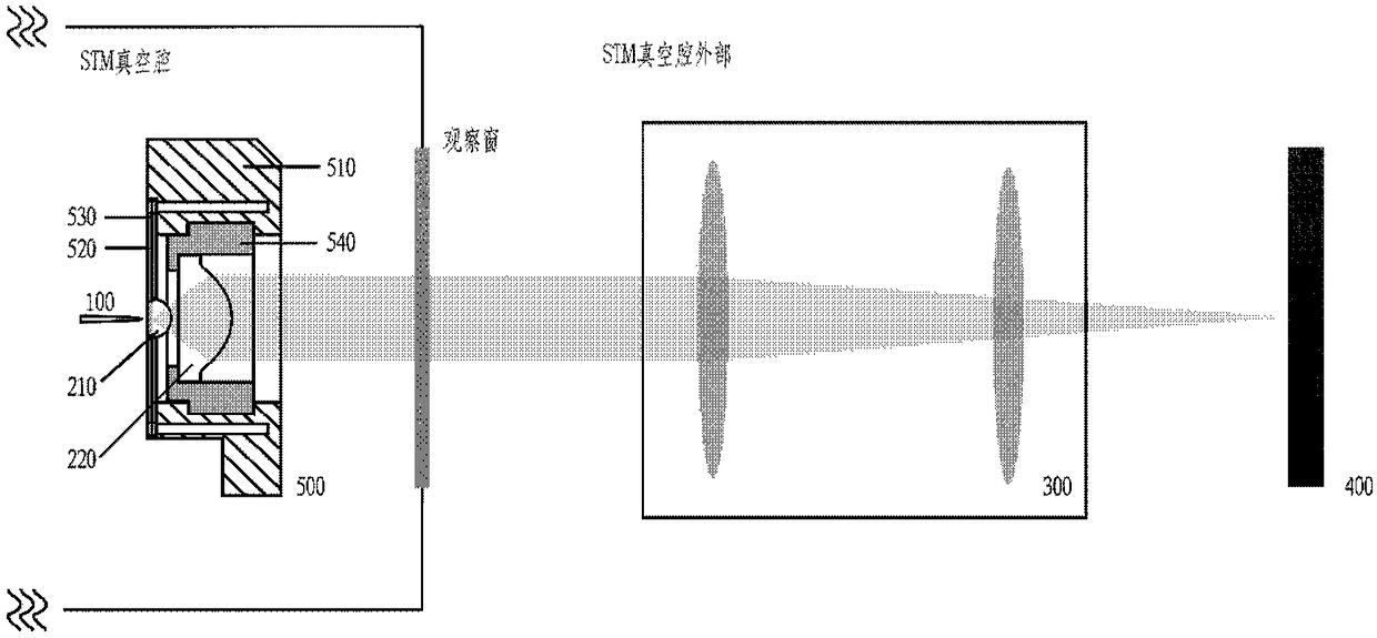
[0056] The disclosure provides a back focal plane imaging device combined with a low-temperature ultra-high vacuum scanning tunneling microscope, including: a sample to be tested, an optical imaging component, an integrated bracket, an extracavity lens group of a scanning tunneling microscope, and an optical detector; The metal is electrically excited to generate surface plasmons on the surface of the sample to be tested. The optical imaging component collects the large-angle optical signal of the leakage radiation formed during the propagation of the surface plasmon and converts it into a parallel optical signal output. The scanning tunneling microscope The extracavity lens group receives parallel light signals for convergence and / or imaging and outputs them, and the optical detector performs spectrum measurement and / or rear focal plane imaging on the received light signals. The disclosure facilitates the imaging of the back focal plane characteristics of the luminescence of t...


PUM


Abstract

The invention provides a back focal plane imaging device combined with a low-temperature ultra-high vacuum scanning tunneling microscope. The device comprises a to-be-measured sample, an optical imaging assembly, an integrated support, an extra-cavity lens group of the scanning tunneling microscope and an optical detector. A metal electrically excites the surface of the to-be-measured sample to generate a surface plasmon, and the optical imaging assembly collects a large-angle optical signal of the radiation leakage formed in the propagation process of the surface plasmon and converts the large-angle optical signal into parallel optical signals for output. The extra-cavity lens group of the scanning tunneling microscope receives the parallel optical signals for convergence and/or imaging and then outputs the signal, and the optical detector performs spectral measurement and/or back focal plane imaging of the received optical signal. The device facilitates imaging of the feature of theback focal plane of the sample illumination and the measurement of associated spectrums in a low-temperature ultra-high vacuum environment.

Description

technical field [0001] The present disclosure relates to the technical field of optical detection, in particular to a back focal plane imaging device combined with a low-temperature ultra-high vacuum scanning tunneling microscope. Background technique [0002] According to the Abbe imaging principle, the spatial frequency information on the Fourier plane (back focal plane) of the lens can represent the radiation direction of the light source, and the spatial angular distribution characteristics of the light source radiation can be obtained by imaging the back focal plane of the lens. In a scanning tunneling microscope (STM), for nanostructures such as molecules and quantum dots placed on the metal interface, the luminescence generally propagates outwards by means of surface plasmons, so the radiation of the relevant surface plasmons is measured The distribution characteristics can reflect the characteristics of nanostructures such as molecules and quantum dots. During the p...

Claims


Application Information

Patent Timeline
Patent Type & Authority Applications(China)
IPC IPC(8): G01Q60/12G01N21/25G01N21/84
CPCG01Q60/12G01N21/25G01N21/84
Inventor 张杨郁云杰范永涛张斗国董振超
Owner UNIV OF SCI & TECH OF CHINA
Why Eureka
Try Eureka