
Underwater adaptive camera housing

a technology of adaptive camera and underwater housing, which is applied in the field of underwater camera housing, can solve the problems of increasing the price of underwater housings for all cameras, introducing additional complexity and diversity, and reducing the field of view, so as to reduce distortion, prevent back reflection, and increase the field of view

Inactive Publication Date: 2009-04-30
OPTIKOS CORP
View PDF14 Cites 70 Cited by
  • Summary
  • Abstract
  • Description
  • Claims
  • Application Information

AI Technical Summary

Benefits of technology

"The present invention is about a camera housing that can be used underwater and has a watertight enclosure. The housing has multiple sections that can be opened and closed, and a transparent window that allows light to enter the housing. The housing also has an adjustable mount for cameras that align with the window. The housing can be used with different types of cameras and has a flat window above the transparent window for emitting strobe illumination. The invention also includes a diffuser to control the pattern of illumination over the scene. The transparent window has a unique shape that reduces back reflection, distortion, and allows for different camera sizes and shapes."

Problems solved by technology

Digital cameras with added displays and menu driven selections for control of camera functions and picture taking settings introduce additional complexity and diversity.
As a consequence, makers of underwater camera housings have been forced to provide designs that match the control requirements of individual camera models.
The fact that each camera requires a unique underwater housing obviously results in higher prices since there is no opportunity to take advantage of economies of scale.
In addition to the problems associated with the need for unique underwater camera housings for every camera, other problems exist with current underwater housings for all cameras.
However, the use of flat windows introduces undesirable distortion and narrows the camera's inherent field of view.
Moreover, housings with flat transmission windows often cause artificial light from a camera to reflect into the camera where it becomes an unwanted part of the photograph thus degrading its quality.

Method used


Image

  • Underwater adaptive  camera housing
  • Underwater adaptive  camera housing
  • Underwater adaptive  camera housing

Examples


Embodiment Construction

[0022]The present invention relates to an underwater camera housing having an adjustable mechanical control interface to adapt it for use with a broad range of camera brands and models. The cameras may be conventional still and video film cameras, digital still and video cameras, or digital devices provided with photographic capability, such as cell phones or PDAs having integrated digital cameras.

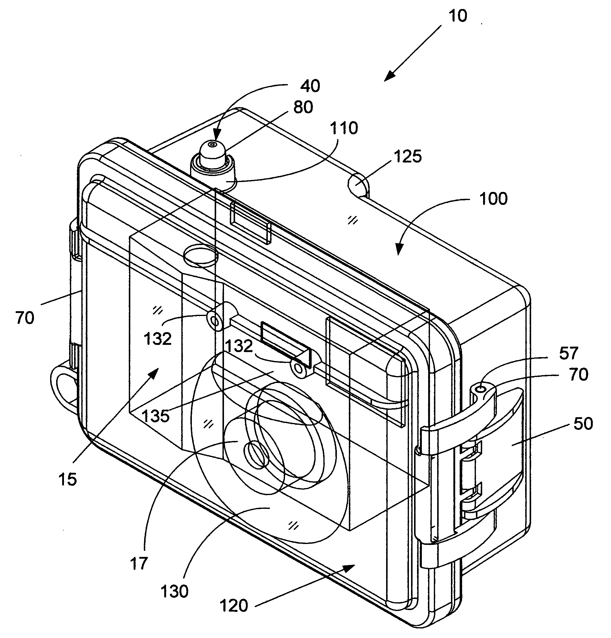
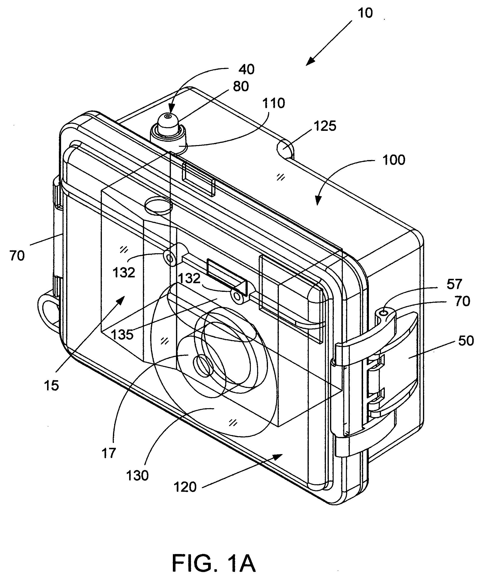
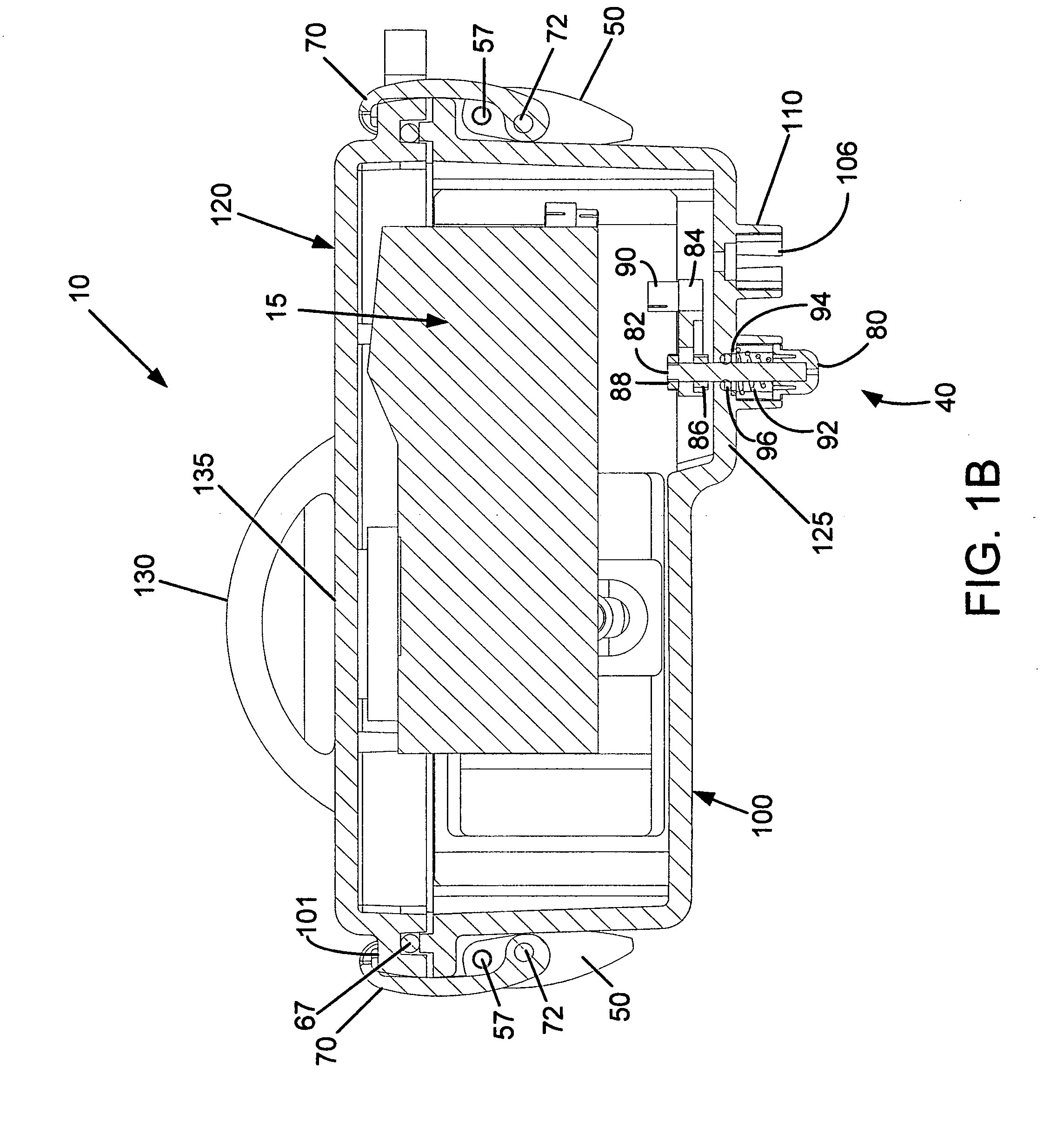
[0023]Reference is now made to FIGS. 1A, 1B, 2 and 3, which show an adaptive underwater camera housing, generally designated at 10, in accordance with the invention, along with a digital camera 15 located inside of housing 10. These figures show, respectively, an upper right front perspective view, a diagrammatic top view, an exploded perspective view, and an upper-rear perspective view of the inventive underwater housing 10 including its control features where FIG. 2 is an exploded perspective view of FIG. 1. As seen in those figures, underwater housing 10 comprises rear and front housing...


PUM


Abstract

An underwater camera housing provided with an adaptive mechanical control arrangement for use with a broad range of camera brands and models. The camera housing is preferably formed of front and rear housing sections that are molded of clear transparent plastic and arranged to be moved between an open position for mounting a camera within the housing and a closed position in which the housing provides a watertight enclosure for protecting and communicating with a camera. The housing is provided with a truncated hemispherical lens through which a camera views scenes to be photographed to reduce distortion and not foreshorten viewing angle and a flat window and optional diffuser for providing controlled artificial illumination to a scene. A mounting plate is structured to slideably fit into one of the housing halves in one of two lateral orientations and includes a slidably adjustable camera mounting plate that permits a user to securely and accurately position cameras side-to-side and for and aft with respect to truncated hemispherical lens. Push button assemblies adjustable in length and point of contact are used to permit a user to adapt them to interact with a variety of camera control actuator architectures.

Description

CROSS-REFERENCE TO RELATED APPLICATION[0001]This application claims the benefit of priority from U.S. Provisional Patent Application No. 61 / 001,012 filed on Oct. 30, 2007 in the name of Stephen J. Fantone, et al. with the title UNDERWATER ADAPTIVE CAMERA HOUSING, the entire contents of which are incorporated herein by reference.BACKGROUND OF THE INVENTION[0002]This invention in general relates to housings for conventional cameras (film or digital, but primarily digital) and other digital devices with integral photographic capability to be used for underwater applications and, more particularly, to underwater camera housings that are adaptable for use with a wide range of cameras having different user interface architectures.[0003]For a variety of reasons, camera manufacturers do not adhere to any standard layout for the arrangement, function, and operation of the controls that must be used in the course of taking pictures. Digital cameras with added displays and menu driven selectio...

Claims


Application Information

Patent Timeline
Patent Type & Authority Applications(United States)
IPC IPC(8): G03B17/08
CPCG03B17/08
Inventor FANTONE, STEPHEN J.FANTONE, STEPHEN D.NIELSEN, PETER M.
Owner OPTIKOS CORP
Learn More