
Working surface bottom plate component and working surface bracket mounting and withdrawing method using same

A technology of working face and floor, applied in the directions of pillar/support, earthwork drilling, transportation and packaging, etc., can solve the problems of affecting the installation and retraction speed of working face, low reuse rate of floor, and no improvement in project efficiency. Environment and floor flatness requirements are not high cost, safe and fast installation and retraction, simple and fast laying and connection effect

Active Publication Date: 2019-02-26
CHNA ENERGY INVESTMENT CORP LTD +1
View PDF3 Cites 0 Cited by
  • Summary
  • Abstract
  • Description
  • Claims
  • Application Information

AI Technical Summary

Problems solved by technology

Due to the heavy weight of the bracket, the effect of partial repair is very poor
With the application of polyurethane polymer materials in coal mines, the laying of floors made of polyurethane polymer materials has also been tried on the working face of inclined coal seams. Its pressure resistance is very poor when used on
The joints of polyurethane polymer materials are not connected smoothly, causing the polyurethane polymer materials to be pulled, disconnected, and errors occur. It is more difficult to handle than the construction of concrete floors, and the purpose of rapid installation and withdrawal has not been achieved.
[0003] At present, the treatment methods for the passageway floor of the installation retraction working face have problems such as long construction period, high production cost, unreliable safety, and spontaneous combustion of the coal seam to varying degrees.
In particular, the retraction working face with a short spontaneous combustion period of the coal seam will inevitably lead to serious consequences of forced closure of the working face due to the long recovery period.
Concrete floors are commonly used to install the bottom plate of the retraction channel on the working face. From concrete transportation, laying to maintenance, the entire construction period generally takes 10 days, and the reliability is poor. During the retraction process, parts are easily damaged and difficult to handle.
Although the bottom plate made of polyurethane polymer material is light, the requirements for the flatness of the bottom plate are too high. Linking the whole, it is easy to slide and deform, which affects the installation and withdrawal speed of the working face, and the reuse rate of the polyurethane polymer material bottom plate is low, and the design and use purpose cannot be achieved through underground use. After a trial installation and withdrawal surface, it cannot be reused again , and the project efficiency has not improved

Method used


Image

  • Working surface bottom plate component and working surface bracket mounting and withdrawing method using same
  • Working surface bottom plate component and working surface bracket mounting and withdrawing method using same
  • Working surface bottom plate component and working surface bracket mounting and withdrawing method using same

Examples


Embodiment Construction

[0058] The specific implementation manner of the present invention will be further described below in conjunction with the accompanying drawings.

[0059] It is easy to understand that, according to the technical solution of the present invention, those skilled in the art can replace various structural modes and implementation modes without changing the essence and spirit of the present invention. Therefore, the following specific embodiments and drawings are only exemplary descriptions of the technical solution of the present invention, and should not be regarded as the entirety of the present invention or as a limitation or restriction on the technical solution of the invention.

[0060] The directional terms such as up, down, left, right, front, back, front, back, top, and bottom that are mentioned or may be mentioned in this specification are defined relative to the structures shown in the drawings, and they are It is a relative concept, so it may change accordingly accord...


PUM


Abstract

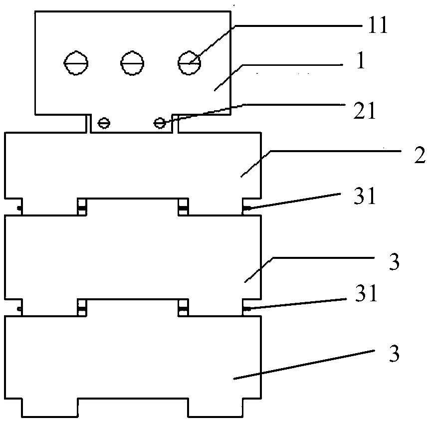
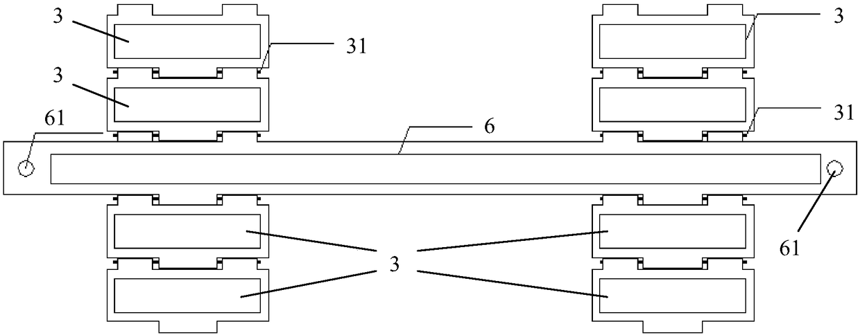
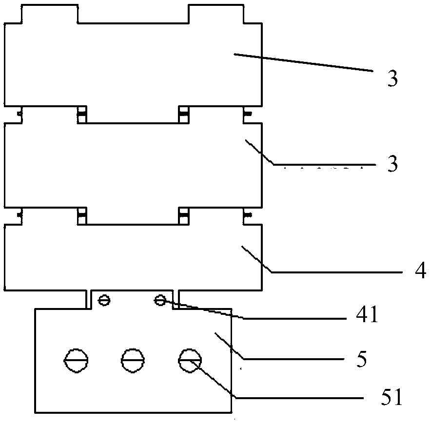
The invention discloses a working surface bottom plate component, which comprises an upper end crawler, an upper transition crawler, a plurality of middle crawlers, a lower transition crawler and a lower end crawler; the upper end crawler is provided with an upper anchor rod fixing hole, the anchor rod is inserted into the upper anchor rod fixing hole and is fixed with the bottom plate; the upperside edge of the upper transition crawler is connected with the lower side edge of the upper end crawler through a first pin shaft, and the lower side edge of the upper transition crawler is connectedwith the upper side edge of the uppermost middle crawler through a shearing pin; the plurality of middle crawlers are connected in sequence, and the adjacent middle crawlers are connected through shear pins; the lower side edge of the middle crawler at the lowest end is connected with the upper side edge of the lower transition crawler through a shearing pin, and the lower side edge of the lowertransition crawler is connected with the upper side edge of the crawler at the lower end part through a second pin shaft; a lower anchor rod fixing hole is arranged on the crawler at the lower end part and the anchor fixing rod is inserted into the lower anchor rod fixing hole and is fixed with the bottom plate. The invention also discloses a working surface bracket mounting and withdrawing method, which can achieve safe and rapid installation and withdrawal of the bracket.

Description

technical field [0001] The invention relates to the technical field of mine mining, in particular to a working face bottom plate assembly and a method for installing and withdrawing a working face support using the working face bottom plate assembly. Background technique [0002] The installation retraction of coal mining face in underground mine is the key work of coal mine safety production, and it is also the key point of mine production cost management. High-yield and high-efficiency mines must use advanced trackless rubber-tyred vehicles to install retraction working faces to be efficient, but trackless rubber-tyred vehicles cannot be used for inclined coal seam mining working faces due to the limitation of climbing angles. At present, each mine first constructs a concrete floor on the bottom plate of the working face channel, and uses a winch to drag the support to the opening of the working face and then uses a trackless rubber-tyred vehicle for installation or recove...

Claims


Application Information

Patent Timeline
Patent Type & Authority Applications(China)
IPC IPC(8): E21F13/06E21D15/58E21D15/60
CPCE21D15/58E21D15/606E21F13/06
Inventor 赵生华胥海东马国军赵凯
Owner CHNA ENERGY INVESTMENT CORP LTD
Learn More