
Self-locking type limited slip differential mechanism

A limited-slip differential, self-locking technology, applied in the field of vehicle components, can solve the problems of differential phenomenon, large space occupation, complex locking structure, etc.

Pending Publication Date: 2019-02-22
李世奇
View PDF4 Cites 1 Cited by
  • Summary
  • Abstract
  • Description
  • Claims
  • Application Information

AI Technical Summary

Problems solved by technology

Cars can generally be divided into road cars and off-road cars according to their uses. When a car is turning, the track distances rolled by the left and right wheels at the same time are often unequal. It is necessary to install a corresponding differential to avoid tire wear, power consumption and fuel consumption, and even cause serious traffic accidents
[0003] At present, most of the existing automobiles use cross-shaft differentials, and their differentials generally do not have an automatic differential locking structure, but a differential lock and an engaging sleeve are added to achieve the locking function. The structure is more complex, it takes up a lot of space, it has high direct damage to the planetary gear, the effect of lock-up control is average, the usability is poor, and the stability is poor, which also brings a certain impact on the life of the entire differential. impact, and cannot meet the environmental protection requirements of energy saving and emission reduction, because the effect is not particularly ideal, especially when encountering ice and snow roads, muddy roads, deep pits, etc., it often occurs that one side of the drive wheel slips and rotates, while the other side drives The wheels stop and do not rotate, causing the vehicle to have a differential speed that cannot move forward, so it is necessary to improve

Method used


Image

  • Self-locking type limited slip differential mechanism
  • Self-locking type limited slip differential mechanism
  • Self-locking type limited slip differential mechanism

Examples


Embodiment Construction

[0023] The following will clearly and completely describe the technical solutions in the embodiments of the present invention with reference to the accompanying drawings in the embodiments of the present invention. Obviously, the described embodiments are only some, not all, embodiments of the present invention. Based on the embodiments of the present invention, all other embodiments obtained by persons of ordinary skill in the art without making creative efforts belong to the protection scope of the present invention.

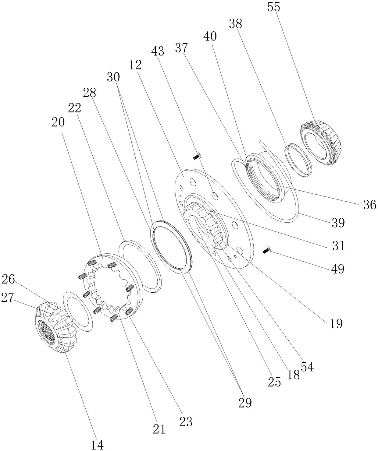
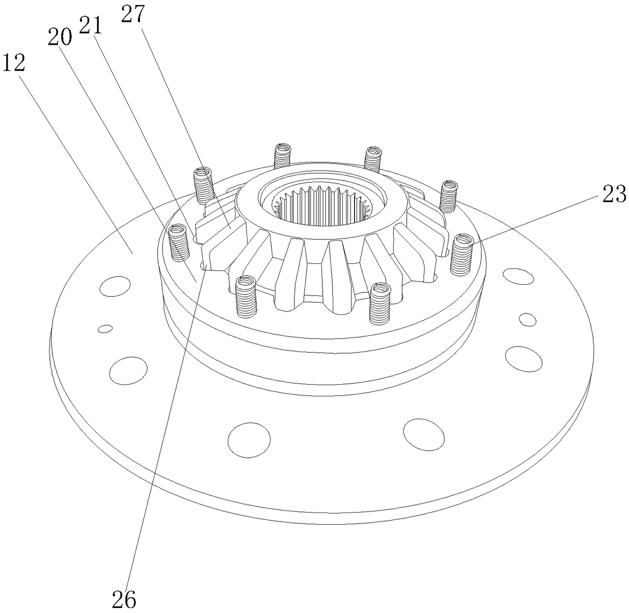
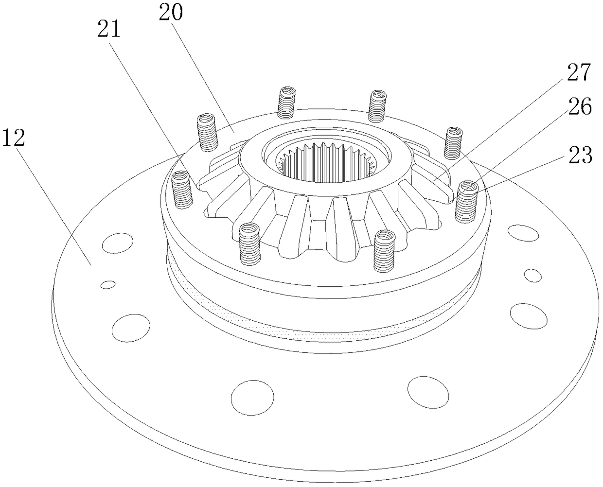
[0024] see Figure 1-8, a self-locking limited-slip differential, including a housing 10, side gears and planetary gears 11, the side gears and planetary gears 11 are installed in the housing 10, and the upper cover of the housing 10 is equipped with a flange cover assembly 12. Side gears include side gears I13 and side gears II14. The housing 10 has shaft holes 15 on the top, bottom and rear side respectively. The shaft holes 15 are equipped with major shafts...


PUM


Abstract

The invention discloses a self-locking type limited slip differential mechanism. The self-locking type limited slip differential mechanism comprises a shell, half axle gears and a planet gear. The shell is covered with a flange cover assembly. The flange cover assembly is provided with an outer tooth meshing guiding structure and an annular groove, the outer tooth meshing guiding structure is sleeved with a meshing locking tooth sleeve internally provided with the inner circle provided with an inner spline, and the inner spline and outer straight teeth on the half axle gear II can be in clamping sleeving fit for locking. A spring hole is formed in the side face of the meshing locking tooth sleeve and internally provided with a reset spring in an abutting manner. A pushing piece is arrangedin the annular groove and can be pushed and ejected out in the annular groove, and an air outlet hole is formed in the bottom of the annular groove. An air pipe is used for air conveying, air entersan air inlet hole through an air cavity, the air pressure is output through the air outlet hole, the pushing piece is pushed through the air pressure, the meshing locking tooth sleeve is subjected tobutting pressing, so that the meshing locking tooth sleeve and the half axle gear II are in a locking state, the differential mechanism is forced to be in a locking state, the differential mechanism has an automatic locking slip limiting function, the weight is reduced, stability is extremely high, and the vehicle passing capability is improved.

Description

technical field [0001] The invention belongs to the technical field of vehicle components, in particular to a self-locking limited-slip differential. Background technique [0002] With the development of the automobile industry and the continuous advancement of technology, people pay more and more attention to the high-end manufacturing of auto parts. Cars can generally be divided into road cars and off-road cars according to their uses. When a car is turning, the track distances rolled by the left and right wheels at the same time are often unequal. It is necessary to install a corresponding differential to avoid tire wear, power consumption and fuel consumption, and even cause serious traffic accidents. [0003] At present, most of the existing automobiles use cross-shaft differentials, and their differentials generally do not have an automatic differential locking structure, but a differential lock and an engaging sleeve are added to achieve the locking function. The st...

Claims


Application Information

Patent Timeline
IPC IPC(8): F16H48/08F16H48/24F16H48/32F16H48/38F16H48/40F16H48/42F16H57/04
CPCF16H48/08F16H48/24F16H48/32F16H48/38F16H48/40F16H48/42F16H57/0424F16H57/043F16H57/0431F16H2048/387
Inventor 李世奇
Owner 李世奇
Learn More