Electromagnetic control engine braking device

A technology of engine braking and electromagnetic control, which is applied in the direction of valve driving devices, engine components, machines/engines, etc., can solve the problems of long time for intervention and exit, unstable transient transition process of the engine, etc., and achieve lifting entry and exit speed, removal of reliability risks, and reduced entry and exit times

Pending Publication Date: 2019-02-22
ZHEJIANG LIMING INTELLIGENT MFG CO LTD
View PDF3 Cites 6 Cited by
  • Summary
  • Abstract
  • Description
  • Claims
  • Application Information

AI Technical Summary

Problems solved by technology

Another example is the use of oil-driven engine braking. The time for engine braking to enter and exit is generally longer (>0.4s), which will affect the transition process of engine braking and ignition states, resulting in unstable transient transition process of the engine.

Method used


Image

  • Electromagnetic control engine braking device
  • Electromagnetic control engine braking device
  • Electromagnetic control engine braking device

Examples


Embodiment Construction

[0062] Embodiments of the present invention will be further described below in conjunction with accompanying drawings:

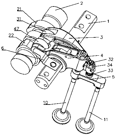
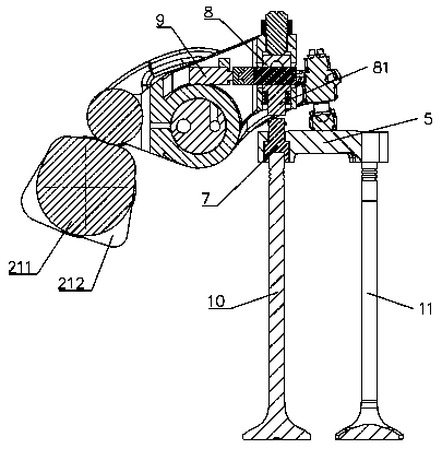
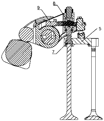
[0063] As shown in the figure, an electromagnetically controlled engine braking device includes a first exhaust valve 10, a second exhaust valve 11, a rocker shaft 1, a camshaft 2, an exhaust rocker 3, an auxiliary rocker 4, Valve bridge 5, elastic member 6, sliding pin 7, action mechanism 8, electromagnetic controller 9.

[0064] The first exhaust valve 10 and the second exhaust valve 11 adopt mushroom valves, which are used to control the flow of gas between the combustion chamber in the engine and the intake and exhaust manifolds.

[0065] The camshaft 2 is arranged parallel to the rocker arm shaft 1, and the camshaft 2 is provided with a first cam 21 and a second cam 22 arranged adjacently; the exhaust rocker arm 3 is adjacent to the auxiliary rocker arm 4 It is rotatably mounted on the rocker shaft 1 , the rear end of the exhaust rocker arm 3 correspon...


PUM


Abstract

The invention provides an electromagnetic control engine braking device. The electromagnetic control engine braking device is characterized in that an action mechanism comprises a sleeve, a cam rod, apush rod and a second elastic part; the sleeve is fixedly mounted in a mounting groove; the cam rod is arranged in a mounting hole; the push rod can slide up and down to be arranged in the mounting groove; the second elastic part drives the push rod to slide upwards to enable the push rod, the cam rod and the sleeve to keep contact with the sleeve all the time; an electromagnetic controller is indriving connection with the cam rod; the push rod has a first position keeping a certain gap from a sliding pin and a second position keeping contact with the sliding pin. The electromagnetic controlengine braking device has the advantages that the cam rod is driven to rotate through the electromagnetic controller to realize switching of the push rod between the first position and the second position; accordingly, an engine is switched between a normal operation state and a braking state; the electromagnetic control engine braking device is simple in structure and more reliable in operation;the using area is increased, the response speed is increased, energy consumption is reduced, and the braking performance of the engine is further optimized.

Description

technical field [0001] The invention is applied to medium and heavy diesel and natural gas engines, and in particular relates to an electromagnetically controlled engine braking device. Background technique [0002] There are many mountains in our country, and the mountain area is vast, accounting for about 69% of the total land area. When heavy trucks travel on long downhill roads in mountainous areas, drivers frequently use the service brake. The service brake can absorb a large amount of energy in a short period of time. As the time increases, the surface temperature of the friction pair between the brake drum and the brake shoe will increase, and the friction coefficient will decrease, which will eventually lead to a dangerous situation of reduced braking performance or even brake failure, causing major traffic accidents. In order to improve the driving safety of heavy-duty commercial vehicles, it is necessary to add an auxiliary braking system on the basis of service br...

Claims


Application Information

Patent Timeline
IPC IPC(8): F01L13/06F01L9/04F01L1/04F01L1/18
CPCF01L1/04F01L1/18F01L13/06F01L9/20
Inventor 俞黎明俞振寰
Owner ZHEJIANG LIMING INTELLIGENT MFG CO LTD
Why Eureka
Try Eureka