Needle clamping mechanism and injection molding system
A pin and collet technology, applied in the direction of coating, etc., can solve problems such as inaccurate positioning of inserts and decline in yield rate, and achieve the effects of improving reliability, determining the action stroke, and ensuring that it is in place
- Summary
- Abstract
- Description
- Claims
- Application Information
AI Technical Summary
Problems solved by technology
Method used
Image
Examples
Embodiment 1
[0073] The present embodiment provides a needle locking mechanism 2, such as figure 2 , image 3 , Figure 6 to Figure 10 As shown, it includes: an installation body, a clamping part and a driving rod 23 .
[0074] Wherein, the clamping part is fixedly installed in the mounting body; the clamping part has a first clamping head 221 and a second clamping head 222 arranged oppositely, and a clamping opening facing outwards is formed between the first clamping head 221 and the second clamping head 222. The holding cavity 223; the driving rod 23 slides toward the opening side of the clamping cavity 223 relative to the installation body, and abuts against the first chuck 221 during the sliding process to reduce the clamping cavity 223, so that the insert It is detachably installed in the clamping cavity 223 .
[0075] In this example, if Figure 9 and Figure 10 shown along the Figure 9 and Figure 10 From right to left in the Y-axis direction, the first chuck 221 includes ...
Embodiment 2
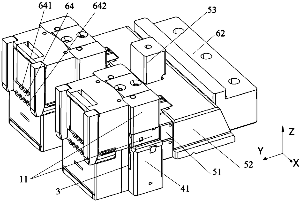
[0098] This embodiment provides a side core pulling mechanism 3, such as figure 2 , Figure 11 to Figure 17 As shown, it includes a mold frame 41 , a linkage component 11 and a sliding body 31 .
[0099] Wherein, the linkage part 11 and the sliding body 31 are stacked on the formwork 41 along the Z-axis direction, and the linkage part 11 is driven by the driving mechanism to slide left and right relative to the formwork 41 along the horizontal Y-axis direction; 11 is driven to slide relative to the mold frame 41 between the mold clamping position and the mold opening position, and the core 33 is installed on the sliding body 31; the limit assembly 32 is telescopically installed on the sliding body along the vertical Z axis direction 31, and the limit assembly 32 is switched between the first limit position and the second limit position in the telescopic direction when the limit component 32 slides with the sliding body 31.
[0100] Specifically, the limiting assembly 32 sli...
Embodiment 3
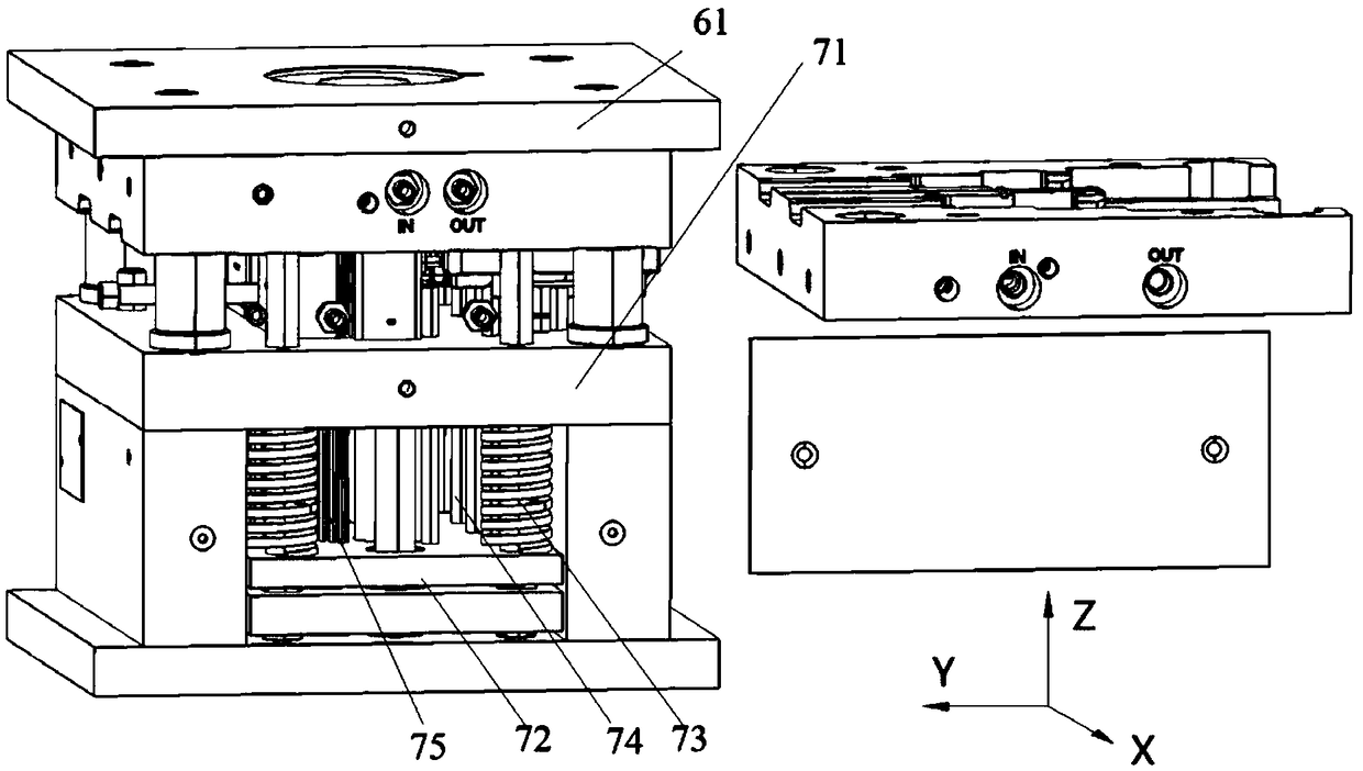
[0126] This embodiment provides an injection molding system, such as Figure 1 to Figure 19 As shown, it includes: the card needle mechanism 2 provided in embodiment 1, the side core-pulling mechanism 3 provided in embodiment 2, the driving mechanism and the linkage components of the side core-pulling mechanism in embodiment 2. The linkage part 11 of the partial structure.
[0127] Among them, such as figure 2 As shown, the locking mechanism 2 is installed in the first passage 17 of the linkage part 11; the first passage 17 is arranged through the linkage part 11 along the Y-axis direction; the side core-pulling mechanism 3 is arranged in linkage at the bottom of the linkage part 11 along the Z-axis direction Above; the drive mechanism includes a drive part 51 arranged on the right side of the linkage part 11 along the Y-axis direction, the drive part 51 drives the linkage part 11 to slide along the Y-axis direction, and the drive part 51 and the linkage part 11 are linked t...
PUM
 Abstract
Description
Claims
Application Information
 - Generate Ideas
- Intellectual Property
- Life Sciences
- Materials
- Tech Scout
- Unparalleled Data Quality
- Higher Quality Content
- 60% Fewer Hallucinations
Browse by: Latest US Patents, China's latest patents, Technical Efficacy Thesaurus, Application Domain, Technology Topic, Popular Technical Reports.
© 2025 PatSnap. All rights reserved.Legal|Privacy policy|Modern Slavery Act Transparency Statement|Sitemap|About US| Contact US: help@patsnap.com


