Puncture oriented addition assembly
A technology of additional components and components, applied in the field of medical devices, can solve problems such as undiscovered product reports, and achieve the effect of ease of use
- Summary
- Abstract
- Description
- Claims
- Application Information
AI Technical Summary
Problems solved by technology
Method used
Image

Examples
Embodiment 1
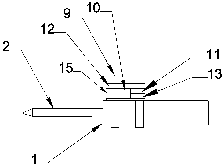
[0049] Such as figure 1 As shown, this embodiment is a puncture orientation add-on assembly, which can be used for ablation needles or puncture needles, including: an orientation assembly and a connecting member for combining with the ablation needle handle;
[0050] The orientation component includes a gyroscope for sensing direction changes, a data processing module for calculating direction information, a display module for displaying direction information, and a peripheral module for providing power to the orientation component.
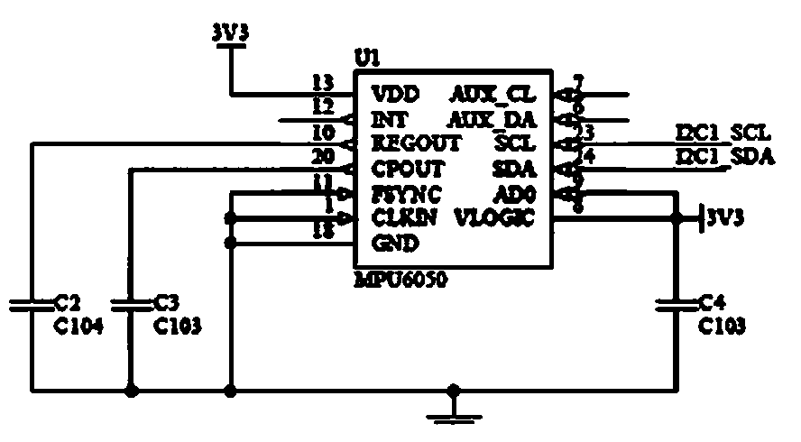
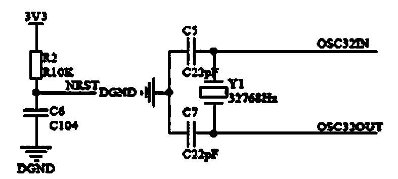
[0051] The directional component is arranged on the front end of the handle 1, so as to check the value; it includes a gyroscope, a data processing module 10, a display module 9, and a peripheral module 11; its internal circuit is as follows: Figure 2 to Figure 11 shown. The components in the orientation assembly are arranged in the following manner in this embodiment: the lower part of the orientation assembly is provided with 1 or 2 sets of e...
Embodiment 2
[0080] Such as Figure 13 , 14 As shown, the present embodiment is a puncture orientation add-on assembly for a puncture needle, including an orientation assembly and a connecting member for combining with a puncture needle handle. Compared with Embodiment 1, the orientation components in this embodiment are the same, but the connecting components are quite different.
[0081] Depend on Figure 13 It can be seen that the puncture needle in this embodiment is different from the ablation needle in that the handle is smaller and square. In this embodiment, the connecting member is arranged on the side of the orientation assembly, so that the overall height of the entire additional assembly is relatively low. The way of connecting the directional components can be a screw connection or a welded or glued connection.
[0082] The connecting member is a card holder type, including a square card holder, clip springs arranged on the inner four walls of the holder, and a bottom spri...
Embodiment 3
[0086] Such as Figure 15 , 16 As shown, the present embodiment is a puncture orientation add-on assembly for a puncture needle, including an orientation assembly and a connecting member for combining with a puncture needle handle. Compared with Embodiment 2, the orientation assembly in this embodiment is the same, and the connecting member adopts a buckle type.
[0087] from Figure 15 , 16 It can be seen that, in this embodiment, the connecting member is fixed on the lower side of the orientation assembly, so that the overall height of the entire additional assembly is relatively high but the length is relatively low. The connecting member used in this embodiment is divided into two parts, both of which are "L" shaped in cross-section. The two parts are connected by hinges and form a box structure after buckling; the left half is fixed to the orientation component, and the front has a The needle head of the needle passes through the arched opening; the contact parts of t...
PUM
 Abstract
Description
Claims
Application Information
 - R&D
- Intellectual Property
- Life Sciences
- Materials
- Tech Scout
- Unparalleled Data Quality
- Higher Quality Content
- 60% Fewer Hallucinations
Browse by: Latest US Patents, China's latest patents, Technical Efficacy Thesaurus, Application Domain, Technology Topic, Popular Technical Reports.
© 2025 PatSnap. All rights reserved.Legal|Privacy policy|Modern Slavery Act Transparency Statement|Sitemap|About US| Contact US: help@patsnap.com