
LED capacitance current-limiting protection circuit

A protection circuit and capacitor current-limiting technology, applied in the field of LED capacitor current-limiting protection circuit, can solve the problems such as the inability to increase the number of LEDs and the inability to form a high-power LED group, achieving a simple structure, solving instantaneous impact, and high circuit efficiency Effect

Inactive Publication Date: 2019-02-19
李少华
View PDF1 Cites 0 Cited by
  • Summary
  • Abstract
  • Description
  • Claims
  • Application Information

AI Technical Summary

Problems solved by technology

[0002] In the patent 200520035646.X, in the first embodiment, a capacitor is used to limit the current, and then a triode is used to output a constant current. In this way, a large current cannot be output to drive a high-current LED. In the second embodiment, although a large current can be output to , but the number of LEDs cannot be increased, and a high-power LED group cannot be formed

Method used


Image

  • LED capacitance current-limiting protection circuit
  • LED capacitance current-limiting protection circuit
  • LED capacitance current-limiting protection circuit

Examples


Embodiment Construction

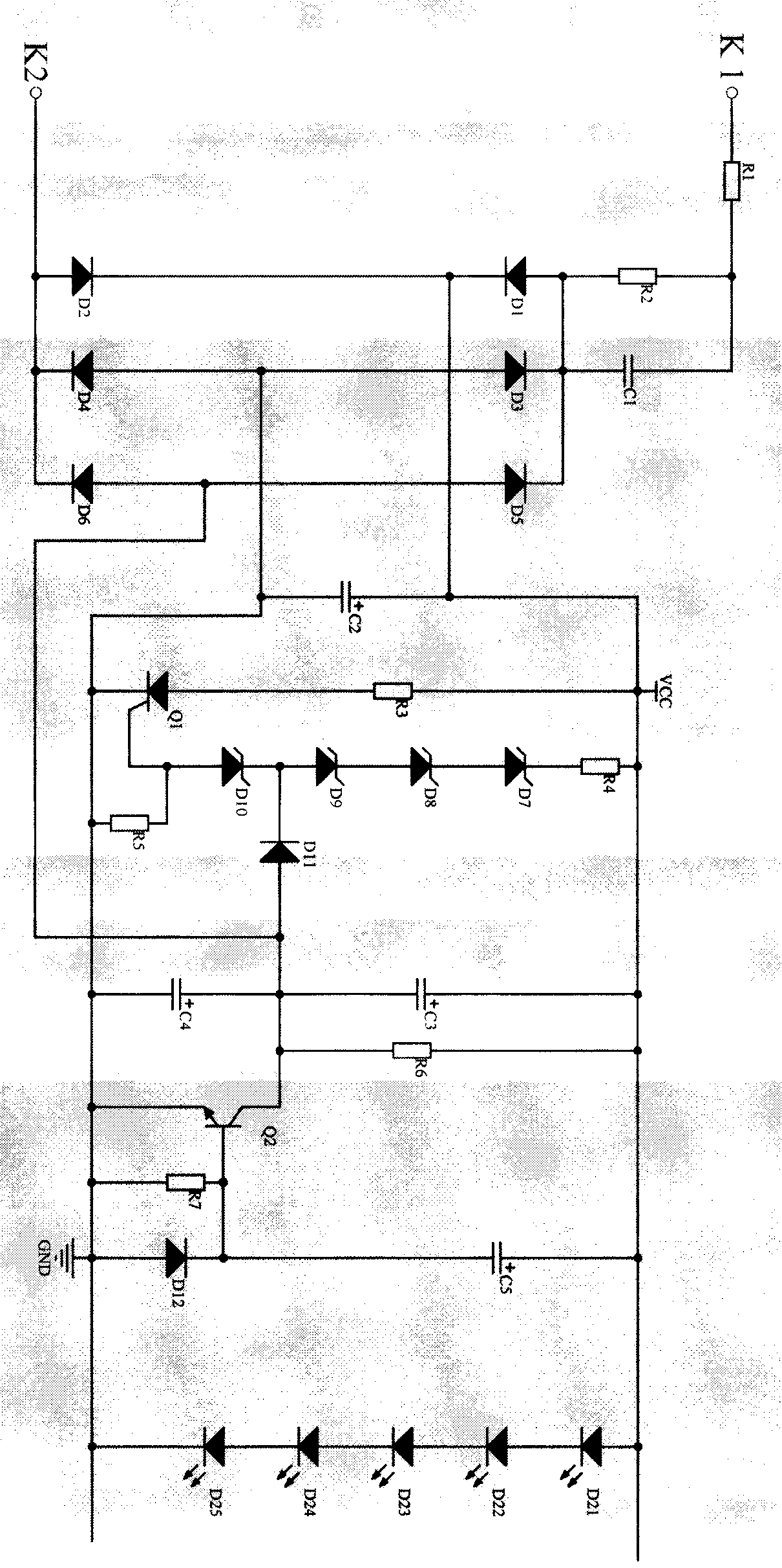
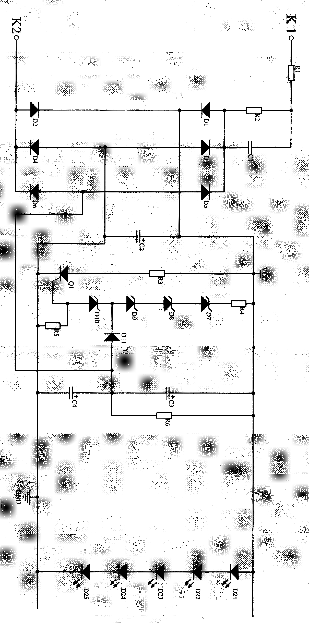
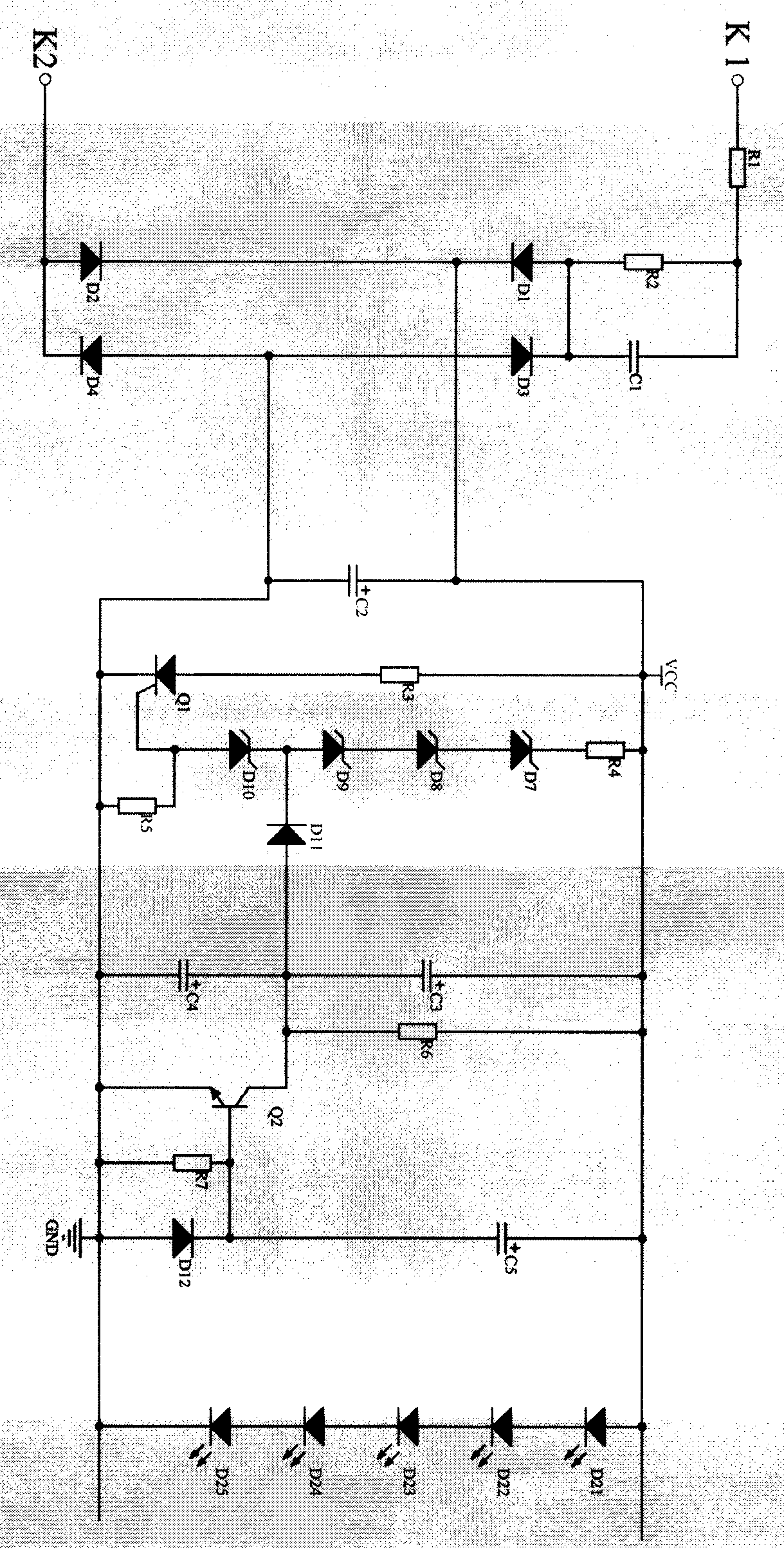
[0013] figure 1 In the LED capacitor current limiting protection circuit, the contacts K1 and K2 are connected to the 220V AC power supply through the switch, the resistor R2 is connected in parallel with the capacitor C1, one end of the resistor R1 is connected to K1, the other end of R1 is connected to one end of C1, the other end of C1 is connected to the anode of diode D1 and diode D3 Negative pole, K2 is connected to the positive pole of diode D2 and the negative pole of diode D4, the negative poles of D1 and D2 are connected to the positive power supply VCC, the positive poles of D3 and D4 are connected to the power ground, the positive pole of capacitor C2 is connected to VCC, the negative pole of C2 is grounded, the positive pole of the LED group is connected to VCC, and the negative pole is grounded. Ground the cathode of the thyristor Q1, connect the anode of Q1 to VCC in series with resistor R3, connect the resistor R5 in parallel between the trigger pole and the cat...


PUM


Abstract

The invention discloses a LED capacitance current-limiting protection circuit. A positive electrode and a negative electrode of a power source are connected by serially connecting a one-way silicon controlled rectifier Q1 with a resistor R3, a voltage stabilizing diode and a resistor R4 are serially connected between a triggering electrode of the Q1 and a positive power source, a resistor R6 and capacitors C2 and C4 form a timing circuit, and diodes D5 and D6 and a triode Q3, a diode D12 and a capacitor C5 enable voltage of the timing circuit to be zero when a LED works. In this way, no resistive device is serially connected between the LED and the power source, so that power loss is reduced, and high-power LED components can be made.

Description

technical field [0001] The invention relates to an LED capacitor current limiting protection circuit, in particular to an LED capacitor current limiting protection circuit. Background technique [0002] In the patent 200520035646.X, in the first embodiment, a capacitor is used to limit the current, and then a triode is used to output a constant current. In this way, a large current cannot be output to drive a high-current LED. In the second embodiment, although a large current can be output to , but the number of LEDs cannot be increased, and a high-power LED group cannot be formed. Contents of the invention [0003] The purpose of the present invention is to overcome the deficiencies in the prior art and provide a LED capacitor current limiting protection circuit. In this circuit, a one-way thyristor Q1 is connected in series with a resistor R3 at the positive and negative poles of the power supply. , between the trigger pole of Q1 and the positive power supply, a voltag...

Claims


Application Information

Patent Timeline
IPC IPC(8): H05B33/08H05B44/00
CPCH05B45/00H05B45/50Y02B20/30
Inventor 李少华李振球
Owner 李少华
Learn More