Programmable fatigue testing machine for handles

A technology of fatigue testing and testing machines, which is applied in the testing of mechanical components, testing of machine/structural components, measuring devices, etc. It can solve the problems of parts cannot be stored, overhauled and maintained, and the test movable plate falls off, so as to achieve normal protection work, reduce maintenance time, and improve work efficiency

Inactive Publication Date: 2019-02-19
广东爱胜德五金制品有限公司
View PDF5 Cites 0 Cited by
  • Summary
  • Abstract
  • Description
  • Claims
  • Application Information

AI Technical Summary

Problems solved by technology

[0004] Although the existing fatigue testing machine is simple in structure and easy to operate, it has a single function. The existing fatigue testing machine cannot provide limit protection for the movable plate of the test during use. When the testing machine breaks down, its testing activities The board is easy to fall off, which is inconvenient. When the existing fatigue testing machine fails, it cannot provide maintenance tools for the staff in time for maintenance, and the disassembled parts cannot be stored, resulting in easy loss. It has a certain adverse effect. The existing fatigue testing machine works for a long time, and the inside of the control box generates high temperature, which causes the internal circuit and components to be easily damaged, and dust and impurities are also easy to enter the inside of the control box through the cooling holes, affecting the internal circuit and components. the normal work of the component, for this purpose, we propose a handle programmable fatigue testing machine

Method used


Image

  • Programmable fatigue testing machine for handles
  • Programmable fatigue testing machine for handles
  • Programmable fatigue testing machine for handles

Examples


Embodiment Construction

[0026] The following will clearly and completely describe the technical solutions in the embodiments of the present invention with reference to the accompanying drawings in the embodiments of the present invention. Obviously, the described embodiments are only some, not all, embodiments of the present invention. Based on the embodiments of the present invention, all other embodiments obtained by persons of ordinary skill in the art without making creative efforts belong to the protection scope of the present invention.

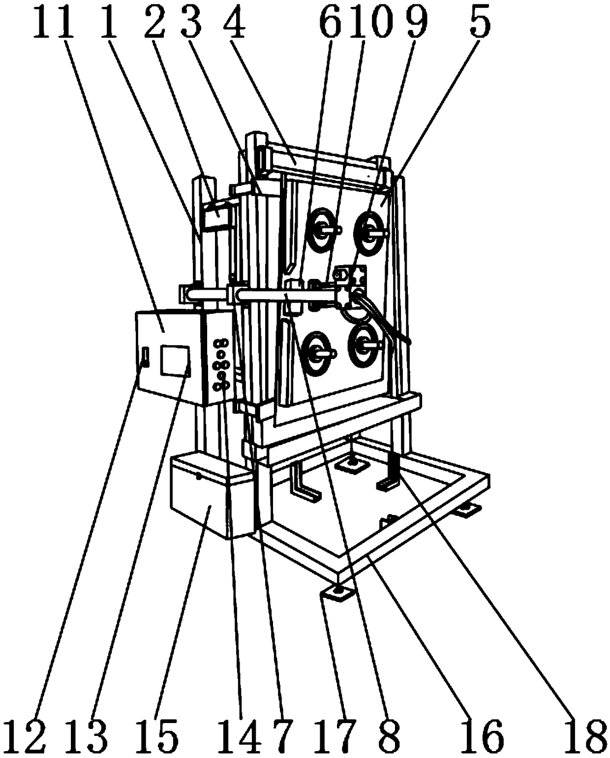
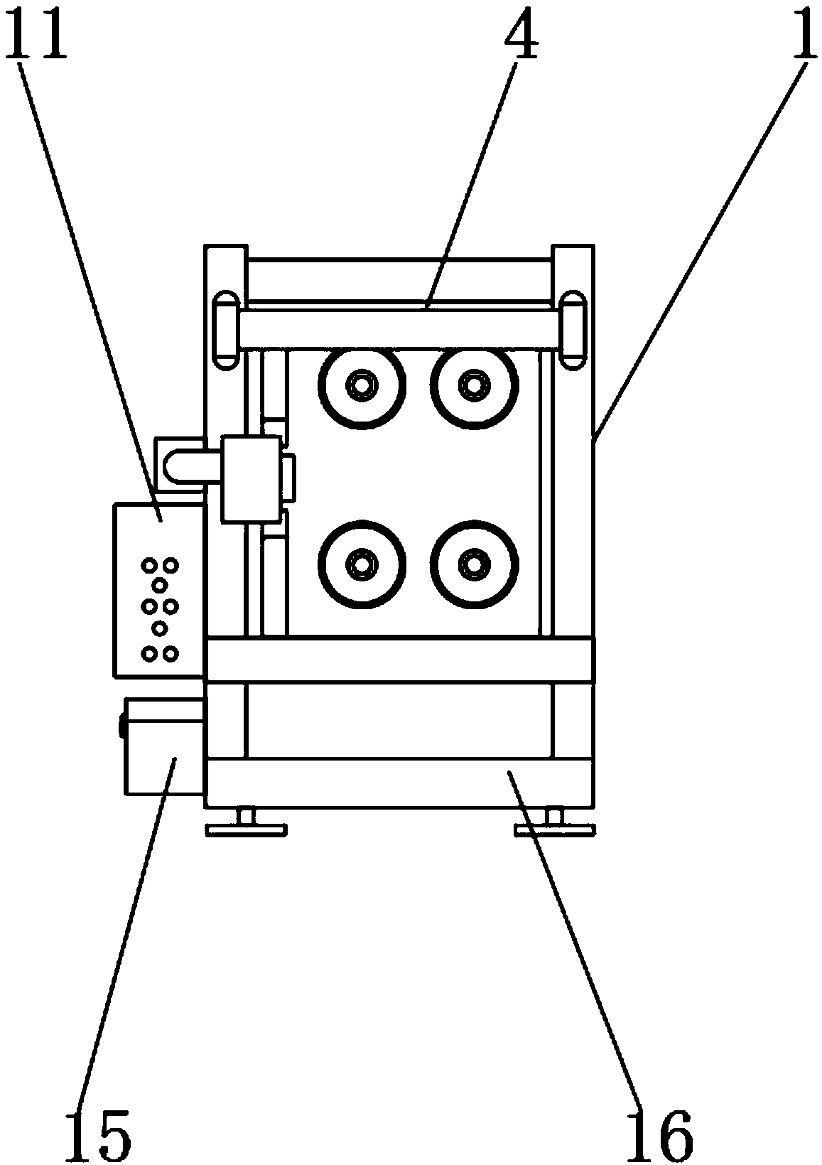
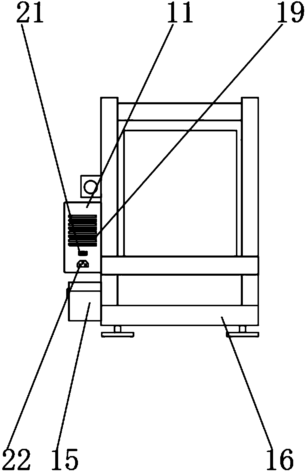
[0027] see Figure 1-7 , the present invention provides a technical solution: comprising a testing machine main body 1, a limit mechanism 4 is fixedly installed on the outer surface of the front end of the test machine main body 1, a hinge mechanism 3 is fixedly installed on the lower end of the limit mechanism 4, and one side of the hinge mechanism 3 is The surface is fixedly connected with a test movable plate 5, the lower end of the hinge mechanism 3 is fix...


PUM


Abstract

The invention discloses a programmable fatigue testing machine for handles, comprising a testing machine main body. A limiting mechanism is fixedly installed on the outer surface of the front end of the testing machine main body. A hinge mechanism is fixedly installed on the lower end of the limiting mechanism. A testing movable plate is fixedly connected with the outer surface of one side of thehinge mechanism. According to the programmable fatigue testing machine for the handles, by means of the limiting mechanism, the impact strength generated by the testing movable plate can be reduced, and the normal work of the testing can be protected; by means of a maintenance mechanism, maintenance tools and parts can be timely provided for workers when a testing machine fails or needs to be maintained, so that the maintenance time is greatly reduced, and the working efficiency is improved; by means of a heat dissipation and dust removal mechanism, the air flow inside a control cabinet can beaccelerated, so that the effect of rapidly cooling the inner portion is realized; and dust and impurities can be prevented from entering the inner portion of the control cabinet through the flowing air flow, so as to protect the internal circuit and components to work normally, so that the service life of the equipment is prolonged indirectly, and the device is convenient to use.

Description

technical field [0001] The invention relates to the field of fatigue testing machines, in particular to a programmable fatigue testing machine with a handle. Background technique [0002] Handle programmable fatigue testing machine is a kind of equipment for testing the service life of the handle. It has high testing efficiency and has been widely used. However, with the development of technology in the times, people have more and more functional requirements for the fatigue testing machine. higher. [0003] During use, the fatigue testing machine can complete the following forms of operation: people can fix the target object to be tested on the testing machine, and test the service life of the target object. [0004] Although the existing fatigue testing machine is simple in structure and easy to operate, it has a single function. The existing fatigue testing machine cannot provide limit protection for the movable plate of the test during use. When the testing machine brea...

Claims


Application Information

Patent Timeline
IPC IPC(8): G01M13/00
CPCG01M13/00
Inventor 郑坤
Owner 广东爱胜德五金制品有限公司
Why Eureka
Try Eureka