
Road sweeper suction nozzle

A technology of road sweeper and suction nozzle seat, which is applied in road cleaning, construction, cleaning methods, etc. It can solve the problems of uneven negative pressure of air flow, limited inhalation particles, and inability to remove them, so as to ensure the suction effect and increase the equivalent diameter. , to avoid the effect of secondary dust

Pending Publication Date: 2019-02-19
福建环海环保装备股份有限公司
View PDF0 Cites 5 Cited by
  • Summary
  • Abstract
  • Description
  • Claims
  • Application Information

AI Technical Summary

Problems solved by technology

[0003] In order to ensure that the suction nozzle has a certain clearance from the ground so as to form an air flow to suck in the garbage, the existing road sweeper has walking wheels at the front and rear of the suction nozzle, and a rubber baffle at the front end of the suction nozzle to control the gap size of the suction inlet. The ground clearance of the suction nozzle is fixed, and the height of the baffle cannot be adjusted, so when it encounters larger garbage, it cannot be removed, that is, the particles of the inhaled matter are limited
Moreover, the suction of the suction nozzle of the existing road sweeper is completely determined by the power of the fan, which cannot be adjusted, and the cleaning rate is often affected by insufficient suction.
There will also be unevenness in cleaning the road. The traditional suction nozzle cannot adjust the ground clearance, which will cause uneven negative pressure of the airflow and affect the cleaning effect.

Method used


Image

  • Road sweeper suction nozzle
  • Road sweeper suction nozzle
  • Road sweeper suction nozzle

Examples


Embodiment Construction

[0021] The present invention will be further described in detail below in conjunction with examples, but the embodiments of the present invention are not limited thereto.

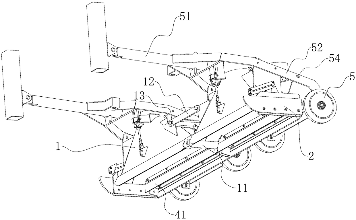
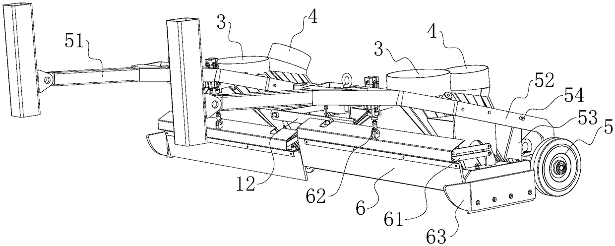
[0022] Such as Figure 1~3 For the preferred solution of the present invention, taking the direction of travel of the front of the car as an example, it includes a left suction nozzle 1, a right suction nozzle 2, a suction tube 3, an air blowing pipe 4, a walking wheel 5 and a baffle plate 6,

[0023] The left suction nozzle 1 and the right suction nozzle 2 are horizontally arranged side by side directly below the vehicle chassis, the bottom of the left suction nozzle 1 and the right suction nozzle 2 is a suction nozzle seat, and a suction cylinder 3 and a dustbin (not shown in the figure) are arranged on the top Link to each other, air blowing pipe 4 is equipped with in the direct rear of suction tube 3 (distinguish front and rear by vehicle advancing direction, the same below), and air blowing pipe 4 link...


PUM


Abstract

The invention discloses a road sweeper suction nozzle. The road sweeper suction nozzle comprises left suction nozzles, right suction nozzles, suction tubes, air blow pipes, walking wheels and baffles,wherein the air blow pipes are arranged in right rears of the suction tubes, the left suction nozzles are hinged with the right suction nozzles, the upper portions of the left suction nozzles and right suction nozzles are connected with movable connecting rods, the rear portions of the left suction nozzles and right suction nozzles are provided with the walking wheels and fixed brackets, the front portions of the left suction nozzles and right suction nozzles are provided with the baffles respectively, the two sides of the baffles are hinged with suction nozzle seats through two parallel connecting rods respectively, and the middles of the baffles are connected with baffle air cylinders. The road sweeper suction nozzle has the advantages that the air blow pipes are arranged to supplementair for the suction tubes, residual garbage is blown to the suction tubes, thereby greatly increasing the cleanness suction rate and effectively avoiding secondary dust raising; the arranged hinged left and right suction nozzles replace a single width suction nozzle so that the suction nozzles can automatically level on the uneven road surface, and the front ends of the suction nozzles are provided with the liftable baffles so as to improve the equivalent diameter of inhalation and the cleanness suction rate.

Description

technical field [0001] The invention relates to the field of sanitation equipment, in particular to a suction nozzle for a road sweeper. Background technique [0002] With the rapid development of urbanization in my country, the cleaning of urban roads has basically been carried out by special sanitation cleaning vehicles. The road sweeper is a commonly used special vehicle for road cleaning. It is generally a structure with a front sweeping plate and a central suction nozzle. The sweeping plate sweeps the garbage into the bottom of the vehicle, and the suction nozzle is provided by the fan to suck the garbage into the garbage bin. [0003] In order to ensure that the suction nozzle has a certain clearance from the ground so as to form an air flow to suck in the garbage, the existing road sweeper has walking wheels at the front and rear of the suction nozzle, and a rubber baffle at the front end of the suction nozzle to control the gap size of the suction inlet. The ground ...

Claims


Application Information

Patent Timeline
Patent Type & Authority Applications(China)
IPC IPC(8): E01H1/08
CPCE01H1/0836
Inventor 周阿滔柏文豪陈令文唐新和简晓河
Owner 福建环海环保装备股份有限公司
Learn More