
Adaptive threshold signal detection method with known duty ratio

An adaptive threshold and signal detection technology, which is applied in transmission monitoring, electrical components, transmission systems, etc., can solve the problems of large amount of calculation, weak signal detection effect, and weak signal detection effect, so as to reduce false alarms The effect of probability

Active Publication Date: 2019-02-15
湖南猎航电子科技有限公司
View PDF13 Cites 0 Cited by
  • Summary
  • Abstract
  • Description
  • Claims
  • Application Information

AI Technical Summary

Problems solved by technology

The above method cannot adapt to the presence of multiple interference signals or the dynamic adjustment of receiver gain
Chinese patent 201110291275.1 proposes a cognitive radio spectrum detection method and device based on adaptive double-threshold, selects the judgment threshold value according to the last judgment result and random noise influence, and then based on the selected judgment threshold value pair The energy value E of the received signal is judged to obtain the judgment result, but this method has poor detection effect on weak signals
Chinese patent 201310344381.0 proposes a signal detection method based on energy detection, which determines whether there is a signal according to the energy variance of the spectrum segment within the system analysis bandwidth, but this method cannot determine the arrival time of the signal
Zhang Yulong et al. proposed a signal detection algorithm based on statistical histograms (Zhang Yulong et al., A signal detection algorithm based on statistical histograms, Military Communication Technology, 2017.3(1):26-30). Based on the generation of graphs and the delineation of noise and signal lines, the signal is divided into signal area, noise area and undetermined area to realize adaptive threshold calculation and judgment. This method has a large amount of calculation and the detection effect on weak signals is not strong.

Method used


Image

  • Adaptive threshold signal detection method with known duty ratio
  • Adaptive threshold signal detection method with known duty ratio
  • Adaptive threshold signal detection method with known duty ratio

Examples


Embodiment Construction

[0030] Below, the present invention will be further described in conjunction with the accompanying drawings and specific embodiments.

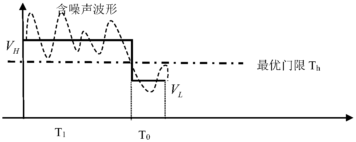
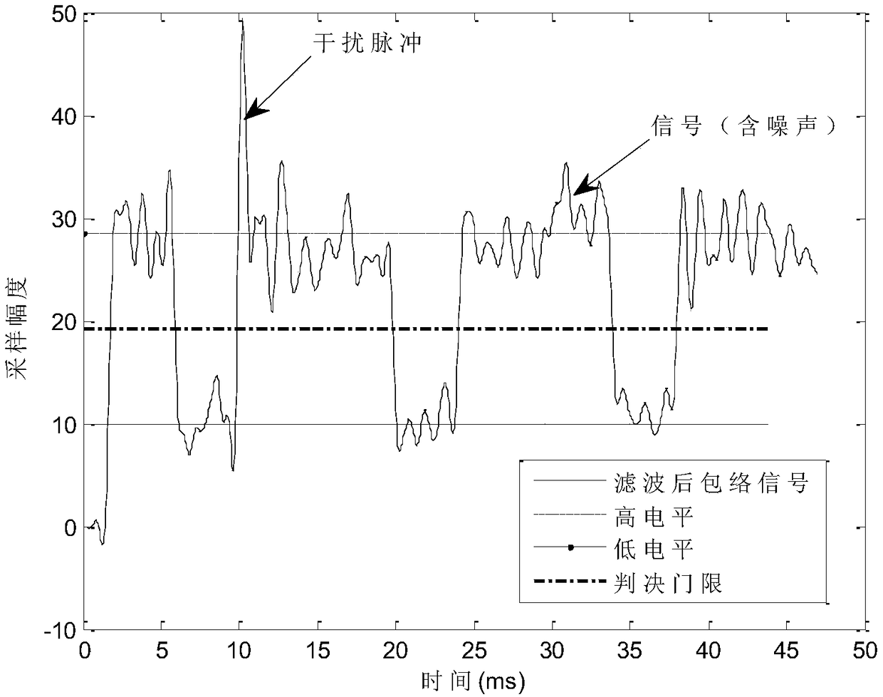
[0031] Such as figure 1 As shown, in the principle of the signal detection method of the present invention, since unknown noise is superimposed in the filtered envelope signal in the figure, how to determine the amplitude V of the signal in the noise-containing waveform H (i.e. high level) and the noise amplitude V L (low level) also becomes an important issue. For this reason, a statistical method can be used, that is, to solve the first-order moment μ and second-order moment V of the above-mentioned signals respectively. It can be known from derivation that the first-order moment and the amplitude V of the signal H (i.e. high level) and the noise amplitude V L (low level) respectively have the following relationship:

[0032]

[0033] Therefore, by solving the above binary quadratic equation, the values ​​of high level and low level c...


PUM


Abstract

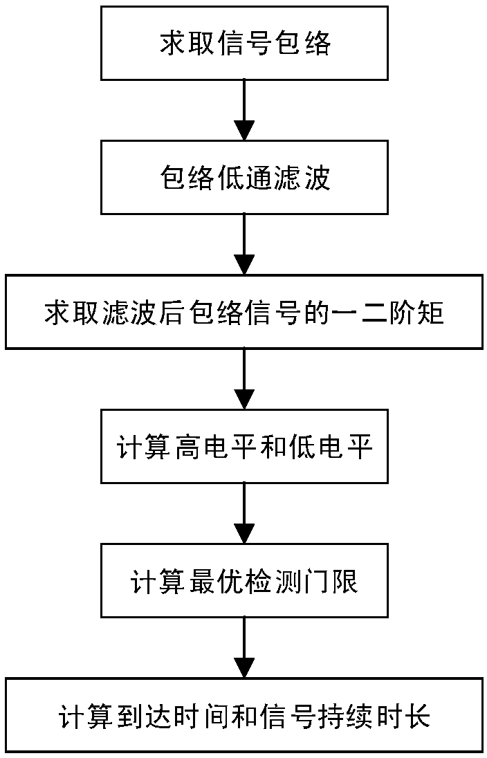
The invention relates to an adaptive threshold signal detection method with a known duty ratio. The method comprises the following steps: firstly, performing low-pass filtering smoothing on a signal envelope; secondly, calculating a mean value and a second-order moment of the filtered signal envelope; and finally, reverse reasoning a high level and a low level of a signal according to the mean value and second-order moment, thereby determining an optimal detection threshold of the signal, realizing the detection of the presence or absence of the signal, and determining the arrival time of thesignal and performing signal duration estimation at the same time. According to the method provided by the invention, the weak signal detection probability with a low signal-to-noise ratio in the presence of a plurality of interference signals is improved, and at the same time, the false alarm probability is reduced; and the method can be applied to the signal detection of anti-radiation unmannedaerial vehicles, and can also be applied to all other cooperative signal detection fields, such as communication multi-user detection, radar signal detection, cognitive radio and the like.

Description

technical field [0001] The invention relates to the field of radio spectrum sensing, in particular to a method for adaptively calculating and detecting a detection threshold under the condition of a known signal duty cycle in the field of anti-drone radio spectrum sensing. Background technique [0002] In recent years, all kinds of civilian or industrial small and medium-sized drones, especially small multi-rotor drones, have not only become emerging professional equipment in various industries, but also become common popular tools in the lives of ordinary people. But it also brings many security threats to low-altitude protection. Since the UAV needs to send back aircraft parameters and image data during flight and shooting so that the operator can control it, the UAV will send out measurement and control and data transmission signals, and the operator will also send out remote control signals. Manufacturers and models of UAV measurement and control and digital transmissio...

Claims


Application Information

Patent Timeline
Patent Type & Authority Applications(China)
IPC IPC(8): H04B17/30H04B17/382
CPCH04B17/30H04B17/382
Inventor 常宇亮卢树军赵征宇
Owner 湖南猎航电子科技有限公司
Learn More