
Triangular rasterized scanning structure based on TLM

A rasterization and triangle technology, applied in the field of triangular rasterization scanning structure, can solve problems such as poor portability, security, reliability, security risks, and restrictions on the independent development of display systems, so as to reduce complexity, improve scanning performance and speed effect

Active Publication Date: 2019-02-15
西安翔腾微电子科技有限公司
View PDF8 Cites 2 Cited by
  • Summary
  • Abstract
  • Description
  • Claims
  • Application Information

AI Technical Summary

Problems solved by technology

Especially in the field of military use, foreign imported commercial GPU chips have hidden dangers in safety, reliability, security, etc., and cannot meet the needs of the military environment; "Blocking" and product "monopoly" make it difficult to obtain the underlying technical information of the GPU chip, such as register information, detailed internal micro-architecture, core software source code, etc., resulting in the inability of GPU functions and performance to be fully utilized, and poor portability; the above problems are serious Restricting the independent research and development of display systems in my country, it is imminent to break through the key technologies of graphics processors and develop graphics processor chips
[0004] At present, the structure used for GPU triangle rasterization scanning is realized through the Zigzag algorithm, but the structure used for GPU triangle rasterization scanning implemented by the Zigzag algorithm, the Y-axis step is too dependent on the end position of the X-axis bidirectional scanning, Increased the complexity of triangle rasterization, affecting the scanning performance and speed of the triangle rasterization scanning structure

Method used


Image

  • Triangular rasterized scanning structure based on TLM
  • Triangular rasterized scanning structure based on TLM
  • Triangular rasterized scanning structure based on TLM

Examples


Embodiment 1

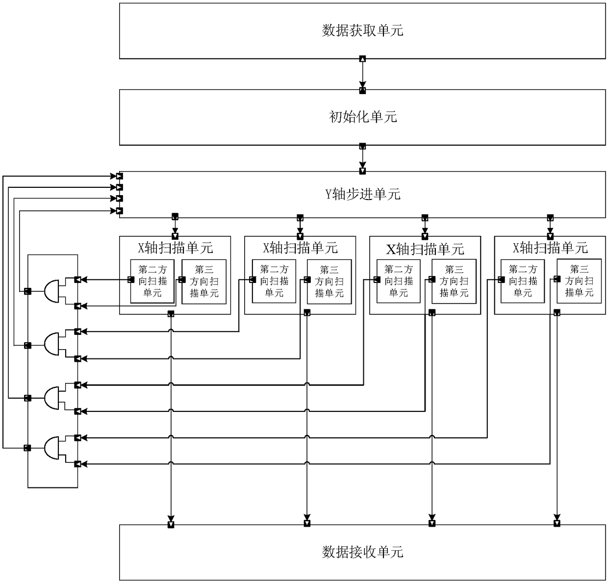
[0030] See figure 1 and figure 2 , figure 1 A schematic diagram of a TLM-based triangular rasterized scanning structure provided by an embodiment of the present invention, figure 2 A schematic diagram of another TLM-based triangular rasterized scanning structure provided by an embodiment of the present invention. A TLM-based triangular rasterized scanning structure provided by an embodiment of the present invention, the rasterized scanning structure includes:

[0031] The data acquisition unit is configured to acquire triangle data information and provide the triangle data information for the initialization unit.

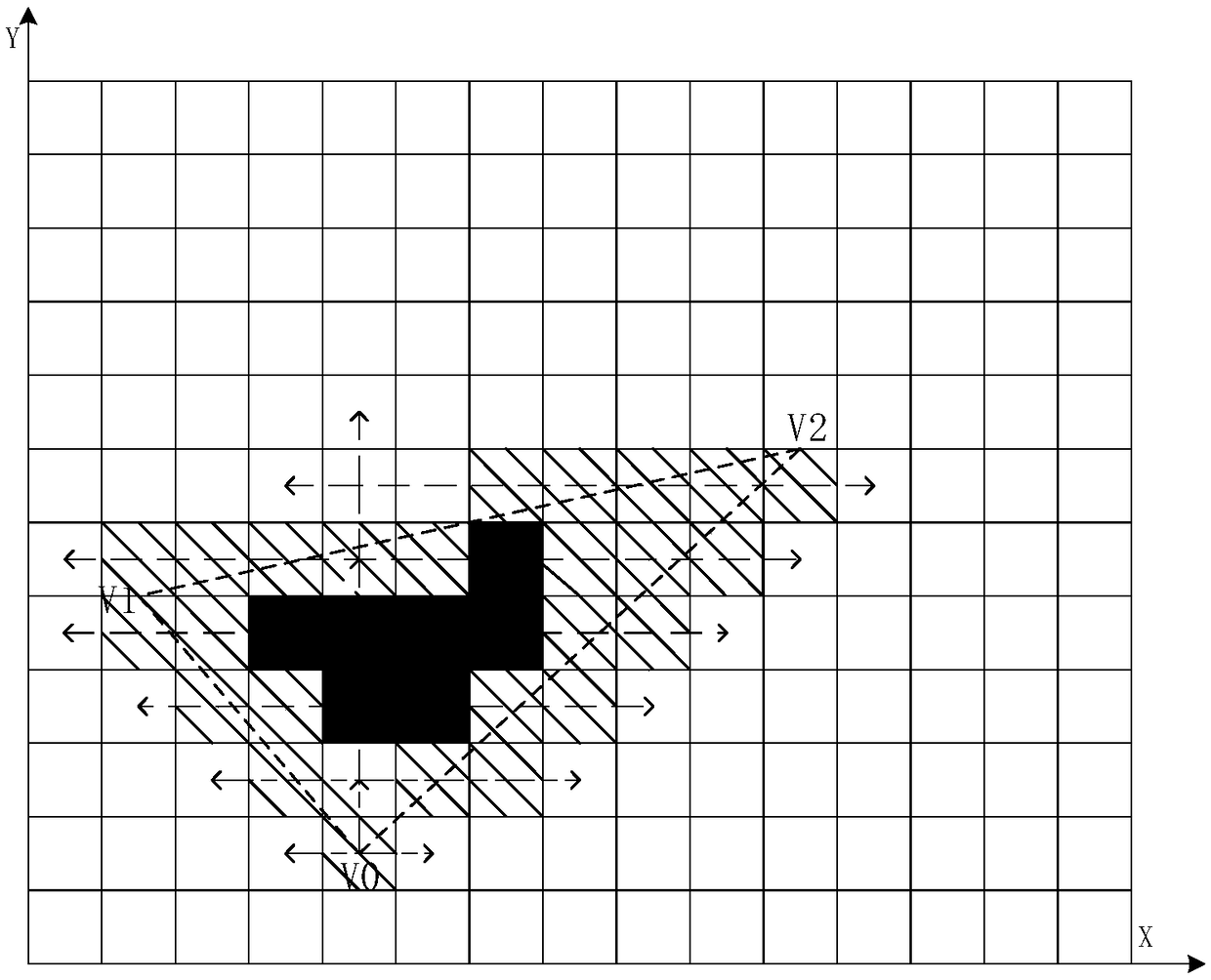
[0032] See image 3 , specifically, the triangle data information is the coordinates of the three points of the triangle, which can be recorded as V0 (x0, y0), V1 (x1, y1) and V2 (x2, y2) respectively, wherein the triangle used for rasterized scanning can be For acute triangles, right triangles and obtuse triangles.

[0033] Preferably, the data acquisition ...


PUM


Abstract

The invention relates to a triangular rasterized scanning structure based on TLM (Transaction Level Models), including an initialization unit which is connected with a data acquisition unit through atransaction level port and is used for receiving triangular data information and obtaining the X-axis starting coordinates and the Y-axis detection range according to the triangular data information,a Y-axis stepping unit which is connected with the initialization unit through a transaction level port and is used for carrying out enabling identification on the X axis and controlling the steppingof detection elements along a first direction according to the Y-axis detection range, and a number of X-axis scanning units which are used for controlling the scanning of the detection elements alongthe X axis according to the enabling identification of the X axis and the X-axis starting coordinates. The triangular rasterized scanning structure integrates the initialization unit, the Y-axis stepping unit and the X-axis scanning units, and the initialization unit, the Y-axis stepping unit and the X-axis scanning units are connected in turn through the transaction level ports, so that X-axis scanning and the Y-axis stepping can be executed in parallel, the complexity of triangular rasterization is reduced, and the scanning performance and speed of the triangular rasterized scanning structure are improved.

Description

technical field [0001] The invention relates to the technical field of computer graphics scanning, in particular to a TLM-based triangular rasterized scanning structure. Background technique [0002] With the continuous increase of graphics applications, the early graphics rendering solutions relying solely on CPU (Central Processing Unit, Central Processing Unit) have been difficult to meet the graphics processing needs of technological growth, so Graphic Processing Unit (GPU) came into being pregnancy. Since the release of the first GPU product by Nvidia in 1999, the development of GPU technology has mainly gone through the fixed-function pipeline stage, the stage of separating the shader architecture, and the stage of unified shader architecture. Rendering gradually extends to the field of general computing. GPU has the characteristics of high-speed pipeline, parallelism and flexible programmability, and provides a good operating platform for graphics processing and gen...

Claims


Application Information

Patent Timeline
IPC IPC(8): G09G5/18
CPCG09G5/18G09G2310/0283
Inventor 李冲刘莎周艺璇杨洋冯迎鸽申越
Owner 西安翔腾微电子科技有限公司
Learn More