Clamp device for automobile ABS brake valve

A fixture device and brake valve technology, applied in the direction of measuring devices, vehicle testing, instruments, etc., can solve the problems of reducing the processing efficiency of the brake valve, the inability to rotate the brake valve, complex structure, etc., and achieve simple structure, easy processing, The effect of improving work efficiency

Active Publication Date: 2019-02-15
YANCHENG GAOYUE MACHINERY
View PDF5 Cites 0 Cited by
  • Summary
  • Abstract
  • Description
  • Claims
  • Application Information

AI Technical Summary

Problems solved by technology

[0003] The existing automotive ABS brake valve fixture device is not only complex in structure, but also cumbersome to operate, which is time-consuming and laborious to use. It can only clamp the brake valve from the side direction, and the brake valve cannot be rotated at different angles, which reduces the processing of the brake valve. work efficiency, for this reason we have proposed a vehicle ABS brake valve fixture device to solve the above problems

Method used


Image

  • Clamp device for automobile ABS brake valve
  • Clamp device for automobile ABS brake valve
  • Clamp device for automobile ABS brake valve

Examples


Embodiment 1

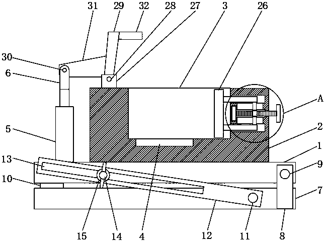
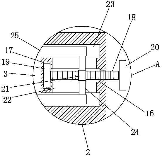
[0025] refer to Figure 1-3 , a kind of automobile ABS brake valve clamping device, comprises base plate 1, and the lower end of base plate 1 is provided with rotating supporting mechanism, and rotating supporting mechanism comprises the base 7 that is arranged on the lower end of base plate 1, and is all fixedly connected on the side walls of both sides of base plate 7 Fixed plate 8, fixed plate 8 is connected on the side wall of base plate 1 through the rotation of first rotating shaft 9, and base plate 1 can rotate around the first rotating shaft 9 on the fixed plate 8, and base plate 1 is fixed on the side wall of the lower end of one end away from fixed plate 8 Two mutually symmetrical support blocks 10 are connected, and the two support blocks 10 are both against the side walls of the base 7, so that the bottom plate 1 is more stable.

[0026] Wherein, the sidewalls on both sides of the base 7 are connected to the limiting plate 12 through the second rotating shaft 11, t...

Embodiment 2

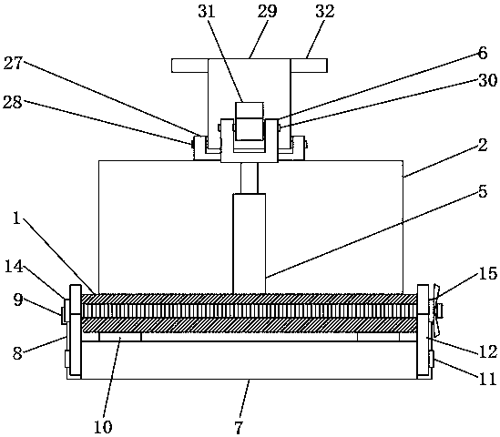
[0031] refer to Figure 4-5 , the difference between this embodiment and Embodiment 1 is that a first rubber pad 33 is fixedly connected to the side wall of the clamping block 26, and a first rubber pad 33 is fixedly connected to the side walls of the first clamping plate 29 and the second clamping plate 32. There is a second rubber pad 34, and the side walls of the first rubber pad 33 and the second rubber pad 34 are provided with protrusions, which can prevent damage to the brake valve and play a certain anti-skid effect when clamping and fixing the brake valve. So that the brake valve can be clamped more securely and firmly.


PUM


Abstract

The invention discloses a clamp device for an automobile ABS brake valve, comprising a bottom plate. The bottom end of the bottom plate is provided with a rotating support mechanism, a placing block is fixedly connected to the side wall of the upper end of the bottom plate, a first placing groove is formed in the side wall of the upper end of the placing block, a second placing groove is formed inthe inner wall of the first placing groove, a clamping mechanism is arranged on the placing block, a cylinder is fixedly connected to the side wall of the upper end of the bottom plate, the output end of the cylinder is fixedly connected to a first concave block, and a pressing mechanism is disposed above the placing block. The clamp device for an automobile ABS brake valve has the advantages ofsimple structure, simple operation, time and labor saving, not only clamping the brake valve from the side direction, but also clamping the brake valve from top to bottom, so that the clamping and fixing of the brake valve is more stable. By using the clamp device, the brake valve can be rotated and processed at different angles according to different requirements, thereby improving the processingefficiency of the brake valve.

Description

technical field [0001] The invention relates to the technical field of clamp devices, in particular to an automobile ABS brake valve clamp device. Background technique [0002] ABS is the anti-lock brake system, which means that the car prevents the tire from locking when braking. If the tire locks, it will lose control of the direction, which can easily cause serious consequences. The ABS brake valve greatly improves the safety of the car. At the same time, because of its simple structure and low cost, it is widely used in light trucks. With the progress of science and technology and economic development in our country, the demand for ABS brake valves is also increasing. According to different needs, ABS The brake valve needs to be further processed. In this process, it needs to be fixed with a special fixture device so that it can occupy the correct position to accept construction or inspection, so that the ABS brake valve can reach the size, geometry and other specificati...

Claims


Application Information

Patent Timeline
Patent Type & Authority Applications(China)
IPC IPC(8): G01M17/007G01M13/00
CPCG01M13/00G01M17/007
Inventor 徐锁
Owner YANCHENG GAOYUE MACHINERY
Why Eureka
Try Eureka