A bollard and its adjustment method

A mooring bollard and adjusting rod technology, applied in shipping equipment, ships, etc., can solve problems such as cable breakage, troublesome adjustment, failure of limit fixing devices, etc., and achieve the effect of avoiding stumbling and simple operation.

Active Publication Date: 2019-08-16
台州道业科技有限公司
View PDF1 Cites 0 Cited by
  • Summary
  • Abstract
  • Description
  • Claims
  • Application Information

AI Technical Summary

Problems solved by technology

[0004] 1. Because the cables tied to the pile body will swing from side to side due to the influence of the weather, in the process of friction with the pile body, not only the cable will be broken, but the cable will also drive the pile body to rotate, so that the adjustment rod and the pile body will rotate relative to each other. Leading to the failure of the limit fixing device, there is a big safety hazard;
[0005] 2. Before work, at least two staff members are required to cooperate. One person pulls up the pile body, and the other person rotates the adjustment lever to limit the position, so the adjustment is troublesome; therefore, it is necessary to improve

Method used


Image

  • A bollard and its adjustment method
  • A bollard and its adjustment method
  • A bollard and its adjustment method

Examples


Embodiment Construction

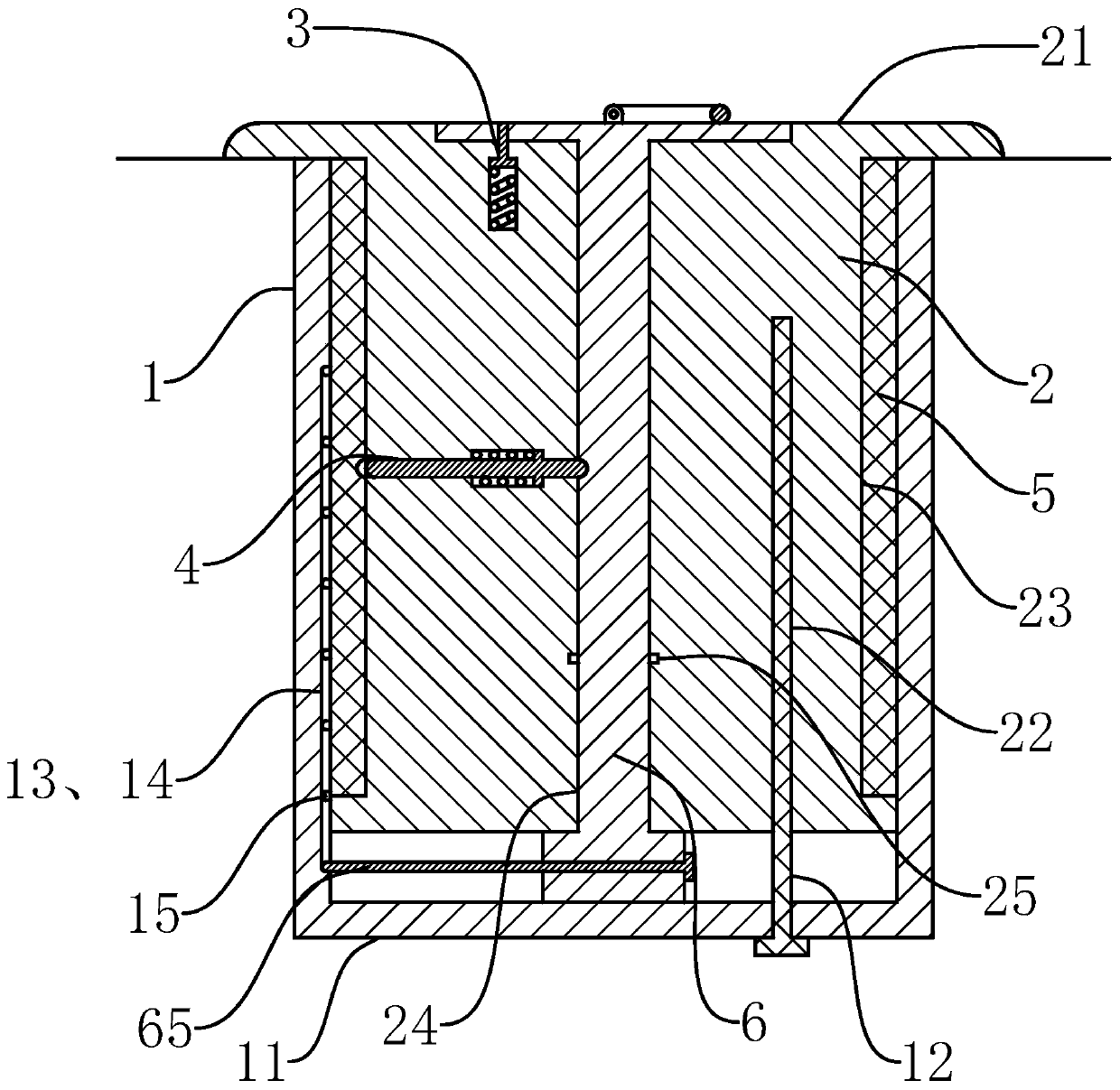
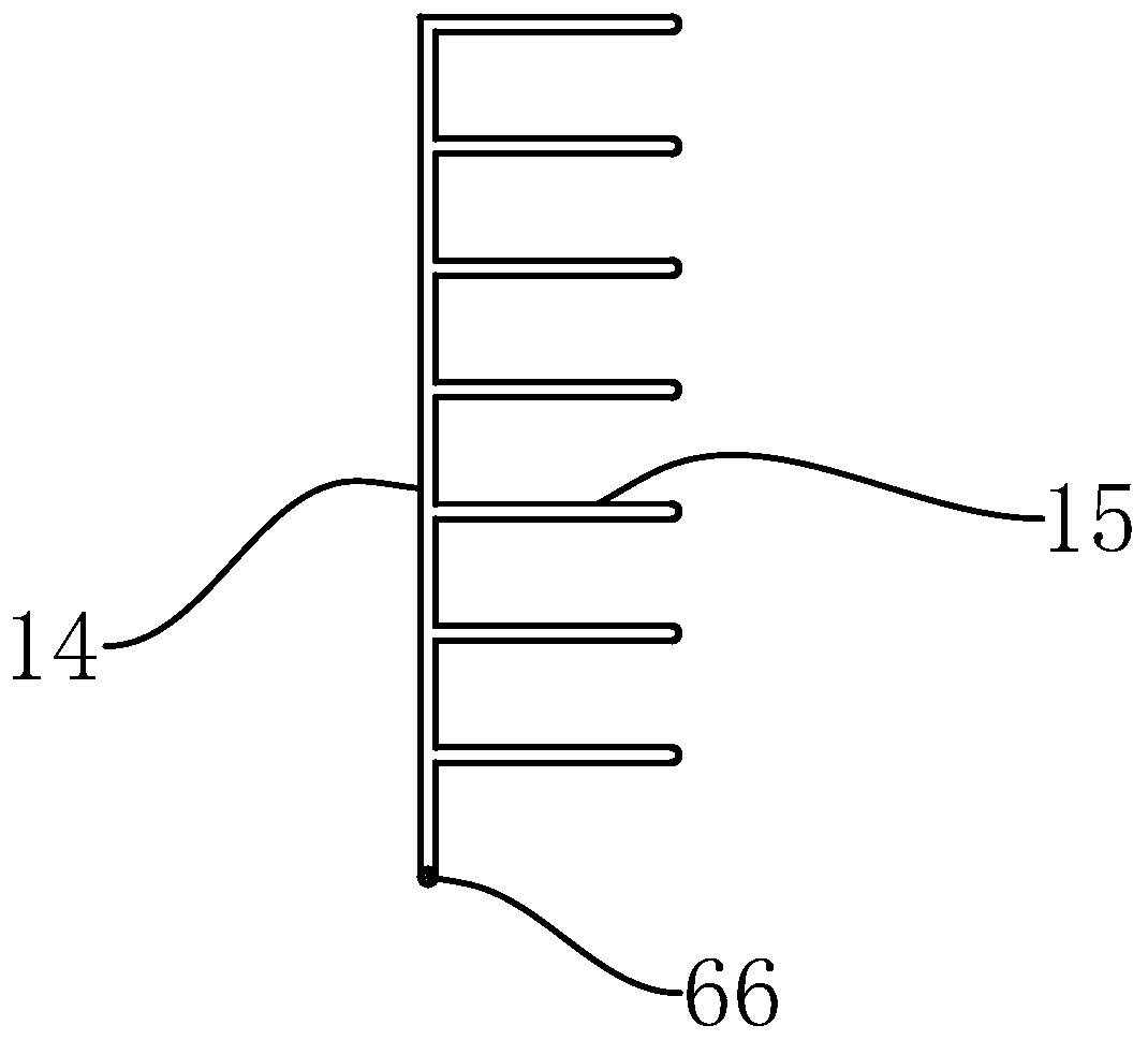
[0042] The following are specific embodiments of the present invention in conjunction with the accompanying drawings to further describe the technical solutions of the present invention, but the present invention is not limited to these embodiments.

[0043] Such as Figure 1-11 As shown, a mooring pile of the present invention includes a cylindrical pile tube 1 embedded below the ground. The top end of the pile tube 1 is flush with the ground. The bottom end of the pile tube 1 is coaxially fixed with a bottom plate 11, and it also includes The cylindrical pile body 2 in the pile tube 1 is coaxially fixed at the top of the pile body 2 with a circular top plate 21. The outer diameter of the top plate 21 is larger than the outer diameter of the pile body 2, and it is also located in the pile tube 1, and the bottom end is fixed to the bottom plate 11. The locating rod 12, the length of the locating rod 12 is parallel to the axis of the pile cylinder 1, the pile body 2 is provided wi...


PUM


Abstract

The invention provides a bitt and an adjusting method thereof, and belongs to the field of bitting equipment. The problem of complex adjusting of an existing bitt is solved. The bitt comprises a bittcylinder. A bottom plate is fixed to the bottom end of the bitt cylinder. The bitt comprises a bitt body embedded in the bitt cylinder. A top plate is fixed to the top end of the bitt body. The bitt comprises a positioning rod located in the bitt cylinder. A positioning groove is formed in the bitt body. The positioning rod is embedded in the positioning groove. A sleeving groove is formed in theouter wall of the bitt body. The bitt comprises a sliding sleeve arranged at the sleeving groove in a sleeving mode. An adjusting hole is formed in the bitt body. The bitt comprises an adjusting rod embedded in the adjusting hole. An adjusting plate is fixed to the top end of the adjusting rod. An adjusting block is fixed to the bottom end of the adjusting rod. A limiting hole is formed in the adjusting plate. A rod groove is formed in the bitt body. An upper limiting rod is located in the rod groove. A limiting groove is formed in the inner wall of the bitt cylinder. The bitt comprises a lower limiting rod fixed to the adjusting block. An inserting hole penetrated by an inserting rod is formed in the bitt body. A front inserting groove is formed in the inner wall of the sliding sleeve. Arear inserting groove is formed in the rod wall of the adjusting rod. A torsion groove is formed in the hole wall of the adjusting hole. A torsion spring is arranged in the torsion groove. The bitt facilitates structure adjusting.

Description

Technical field [0001] The invention belongs to the technical field of mooring equipment, and relates to a mooring pile and an adjustment method thereof. Background technique [0002] Mooring bollards are devices for mooring cables installed on the wharf or deck. The existing mooring bollards are generally fixed structures, which are protruding structures when not in use, which will take up space and cause certain safety hazards to passing vehicles and pedestrians; [0003] The existing application number is 201710489072.0, a Chinese invention patent application titled "a hidden mooring pile", which discloses a mooring pile with an adjustable structure. Under normal circumstances, the adjustment block is placed on the mooring pile. The placement of the barrel can avoid affecting vehicles and pedestrians. When working, pull the pile from the placement barrel upward and fix it with a limit fixing device to use the pile. But it has the following problems: [0004] 1. Because the cable...

Claims


Application Information

Patent Timeline
Patent Type & Authority Patents(China)
IPC IPC(8): E02B3/20B63B21/06
CPCB63B21/06E02B3/20
Inventor 张丽丽
Owner 台州道业科技有限公司
Why Eureka
Try Eureka