


Quick Research
Generate reliable direction feasibility study reports for your R&D in just a few steps.

Technical Q&A
Discover and master advanced knowledge NOW. Basics, ideas, possibilities, all at once.

Find Solutions
As an expert in R&D theories, this can generate solutions to your technical problems instantly.

Evaluate Feasibility
Analyze your overall solution with one click, know your potential R&D risks in advance.

Monitor Landscape
Get weekly tech updates, stay abreast of the latest tech innovations and key insights.
A mobile cable pulling device in the process of electric power construction
A technology of cable traction and electric power construction, which is applied in the field of electric power devices, can solve problems such as not being able to satisfy the simultaneous traction of multiple cables, and achieve the effects of reducing work load, facilitating movement, and enhancing contact area
- Summary
- Abstract
- Description
- Claims
- Application Information
AI Technical Summary
Problems solved by technology
Method used
Image

Examples
Embodiment 1
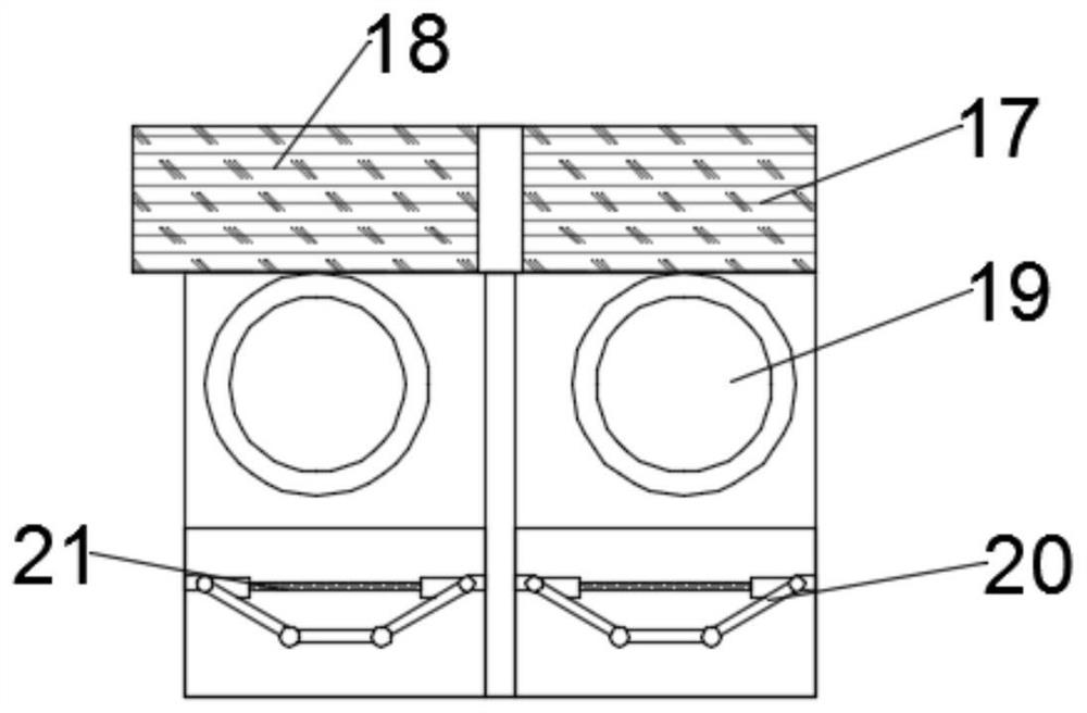
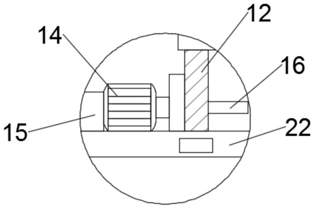
[0019]SeeFigure 1~3In the embodiment of the present invention, a traction mechanism includes a second working motor 14, a battery 15, a traction roller 17, and a support plate 20. The second working motor 14 is provided with a battery 15 on the left side, and the second working motor 14 It is electrically connected to the storage battery 15. The storage battery 15 supplies power for the operation of the second working motor 14. The right side of the second working motor 14 is fixedly welded to the third rotating shaft 16, and the third rotating shaft 16 is fixed at one end away from the second working motor 14. The traction roller 17 is welded. The traction roller 17 is in the shape of a roller. A plurality of support plates 20 are arranged under the traction roller 17, and a cable 19 is arranged between the traction roller 17 and the support plate 20. The cross section of the support plate 20 is In an inverted isosceles trapezoid, a third rotating shaft 21 is rotatably installed on...
Embodiment 2
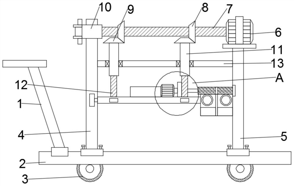
[0027]SeeFigure 4 In the embodiment of the present invention, the left side of the upper surface of the movable base 2 is fixedly connected to the left support column 4 by bolts, the first working motor 6 is fixedly installed on the movable base 2, and the first working motor 6 The left end of the first working motor 6 is fixedly welded to the left end of the first rotating shaft 7. Two first bevel gears 8 are installed on the first rotating shaft 7. A second bevel gear 9 is arranged above the first bevel gear 8, and the first The bevel gear 8 meshes with the second bevel gear 9. The upper part of the second bevel gear 9 is welded with an internally threaded sleeve 11, which is threadedly connected to the second rotating shaft 12, and the upper end of the second rotating shaft 12 is hinged to the worktable 22, The left end of the workbench 22 is slidably connected to the left support column 4, and a traction mechanism is installed on the right side of the upper surface of the workbe...
PUM
 Abstract
Description
Claims
Application Information
 - R&D Engineer
- R&D Manager
- IP Professional
- Industry Leading Data Capabilities
- Powerful AI technology
- Patent DNA Extraction
Browse by: Latest US Patents, China's latest patents, Technical Efficacy Thesaurus, Application Domain, Technology Topic, Popular Technical Reports.
© 2024 PatSnap. All rights reserved.Legal|Privacy policy|Modern Slavery Act Transparency Statement|Sitemap|About US| Contact US: help@patsnap.com