
Inductive thermal imaging non-destructive testing system based on novel high-efficiency open magnetic yoke coil structure

A yoke coil and non-destructive testing technology, which is applied in the direction of material magnetic variable and material defect testing, etc., can solve the problems of negative impact of defect detection, small detection area, small magnetic induction intensity, etc., and achieve good detection effect, uniform eddy current, eddy current enhanced effect

Active Publication Date: 2019-02-12
四川沐迪圣科技有限公司
View PDF13 Cites 6 Cited by
  • Summary
  • Abstract
  • Description
  • Claims
  • Application Information

AI Technical Summary

Problems solved by technology

However, they have the following disadvantages in the detection process: the magnetic field generated by the excitation in the test piece is not uniform and the magnetic induction intensity is small; Small area, low detection efficiency, etc.
At the same time, when the existing technology detects specimens with complex geometric structures, due to the edge effect and proximity effect of induction heating, it will have a negative impact on defect detection

Method used


Image

  • Inductive thermal imaging non-destructive testing system based on novel high-efficiency open magnetic yoke coil structure
  • Inductive thermal imaging non-destructive testing system based on novel high-efficiency open magnetic yoke coil structure
  • Inductive thermal imaging non-destructive testing system based on novel high-efficiency open magnetic yoke coil structure

Examples


Embodiment

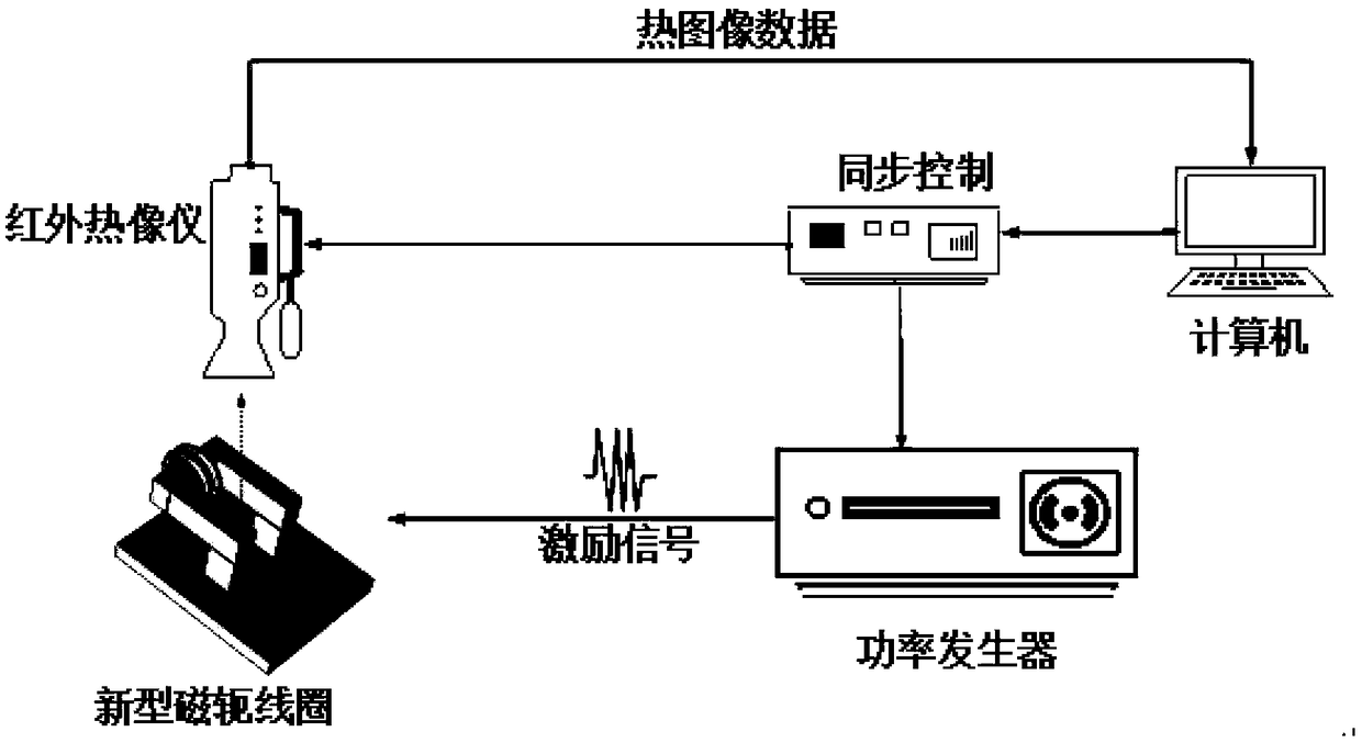
[0036] image 3 It is the principle diagram of the induction thermal image non-destructive testing system based on the new high-efficiency yoke coil structure of the present invention.

[0037] In this example, if image 3 As shown, the present invention is an induction thermal image non-destructive testing system based on a new high-efficiency yoke coil structure, including: a power generator, an infrared camera, a computer, a synchronous controller and a new high-efficiency yoke coil.

[0038] Wherein, the synchronous controller is respectively connected with the power generator, the external trigger port of the infrared thermal imager and the computer interface, and generates the synchronous control pulse signal of the power generator and the infrared thermal imager according to the parameters set by the computer;

[0039] The power generator is used to generate alternating excitation current and pass it into the excitation coil; the infrared thermal imager is used to coll...


PUM

PropertyMeasurementUnit
Diameteraaaaaaaaaa

Abstract

The invention discloses an inductive thermal imaging non-destructive testing system based on a novel high-efficiency open magnetic yoke coil structure. Through use of a novel high-efficiency magneticyoke coil for replacing the conventional rectilinear wire coil or circular coil, the radiation intensity of a test specimen in any direction is directly proportional to the cosine of the included angle between an observing direction and the normal line of a radiating surface, namely radiation of the test specimen in the normal direction of the radiating surface is the strongest; in addition, a uniform eddy current field is sensed in the test specimen, and a visual field is provided for an infrared thermal imager to acquire thermal field information in the test specimen.

Description

technical field [0001] The invention belongs to the technical field of non-destructive testing, and more specifically relates to an induction thermal imaging non-destructive testing system based on a novel high-efficiency split yoke coil structure. Background technique [0002] Non-destructive testing technology is based on the premise of not destroying the internal structure of the object under test, and applies physical methods to detect the physical properties, state characteristics and internal structure of the object inside or on the surface, and check whether there is discontinuity inside the object, so as to judge whether the object under test is qualified , and evaluate its applicability. It is an important means to control product quality and ensure the safe operation of in-service equipment. Pulsed eddy current thermal imaging (ECPT) technology is a thermal imaging detection technology that uses current as a heat source. It combines the advantages of eddy current ...

Claims


Application Information

Patent Timeline
IPC IPC(8): G01N25/72G01N27/90
CPCG01N25/72G01N27/90
Inventor 高斌刘泽伟
Owner 四川沐迪圣科技有限公司
Learn More