
Engine induction manifold

A technology of intake manifold and engine, which is applied in the direction of combustion engine, machine/engine, internal combustion piston engine, etc. It can solve the problems of uneven eddy current and achieve the effect of uniform eddy current and simple structure

Inactive Publication Date: 2007-02-14
ANHUI DACHANG TECH
View PDF0 Cites 5 Cited by
  • Summary
  • Abstract
  • Description
  • Claims
  • Application Information

AI Technical Summary

Problems solved by technology

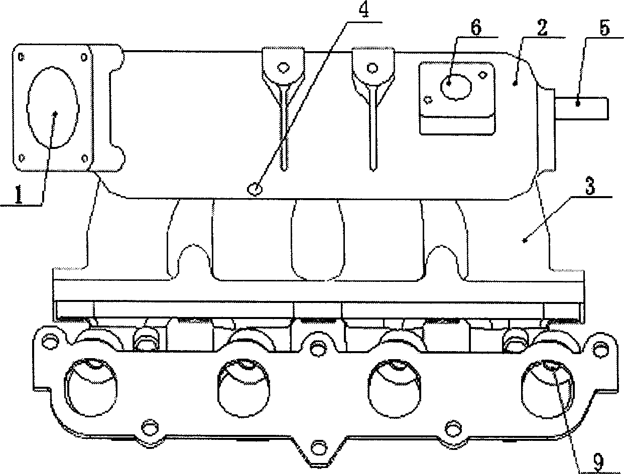
[0003] The present invention solves the existing technical problems such as uneven vortex generated by each cylinder of the engine intake manifold, and is suitable for the needs of modern central control multi-cylinder engine control, and provides an engine intake manifold. The engine intake manifold not only It has the characteristics of equal flow in each cylinder, uniform eddy current generation, and simple structure

Method used


Image

  • Engine induction manifold
  • Engine induction manifold
  • Engine induction manifold

Examples


Embodiment Construction

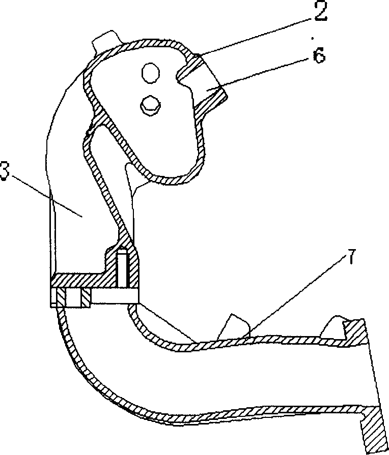
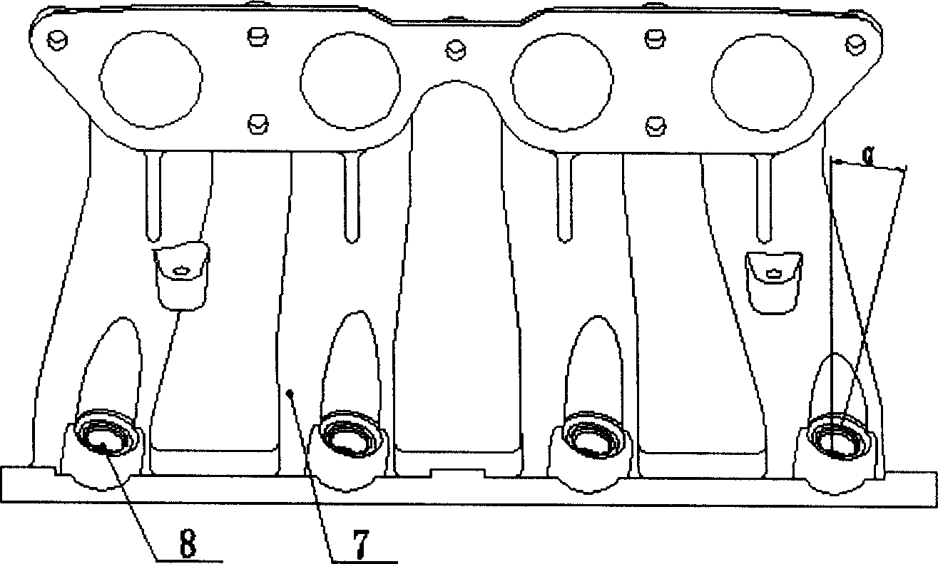
[0017] exist figure 1 , 2 In the four-cylinder engine intake manifold embodiment shown in , 3 and 4, an engine intake manifold includes an upper body that collects flow and a lower body that disperses flow. The upper body has an air inlet 1, a resonance cavity 2 and a set of bent upper body tubes 3; the lower body has a set of lower body tubes 7 adapted to the bent upper body tubes 3, and electrospray holes 8 And air outlet 9. The upper body is also provided with a sensor mounting hole 6, a crankcase ventilation pipe joint 4 and a vacuum pipe joint 5, and a group of bent upper body pipes 3 are arranged in parallel. The crankcase ventilation pipe joint 4 is located in the middle of the upper body, and the vacuum pipe joint 5 is located at the tail end of the upper body.

[0018] Such as image 3 As shown, the angle between the electrospray hole 8 and the vertical plane is 13--15°.


PUM


Abstract

An air inlet manifold of engine consists of flow concentration top body and flow dispersion bottom body. It is featured as setting air inlet and resonant cavity as well as a group of folded top body tube on said top body, setting air outlet and electric jet hole as well as bottom body tube adapting to top body tube on said bottom body, also setting erection hole of transducer and vacuum pipe fittings as well as air ventilation pipe fitting of crankcase on said top body, and setting a group of folded top body tube to be in parallel way.

Description

technical field [0001] The invention relates to an engine intake manifold, in particular to a centrally controlled multi-cylinder engine intake manifold. Background technique [0002] At present, the structure of the traditional engine intake manifold is that a group of dredging air pipes are drawn radially from the resonance cavity of the collector upper body. Its shortcomings are that the airflow entering each cylinder (especially those with four or more cylinders) is not uniform, the eddy current generated by each cylinder is not uniform, and the angle of the electric injection hole of each cylinder is not easy to control, resulting in the decline of injection quality and poor combustion. Emissions worsened. Moreover, the traditional engine intake manifold does not have various sensor mounting holes necessary for modern centrally controlled multi-cylinder engines. Contents of the invention [0003] The present invention solves the existing technical problems such as u...

Claims


Application Information

Patent Timeline
IPC IPC(8): F02B31/00
CPCY02T10/146Y02T10/12
Inventor 杨启明钟华山钱根来熊亚军钱炳南程融张宏越张李华
Owner ANHUI DACHANG TECH
Learn More