
Lathe for positioning and locking main shaft circumference

A positioning locking and circumference technology, which is applied in the direction of woodworking lathes, turning equipment, tool holder accessories, etc., can solve the problems of not being able to expand the application range of machine tools, fewer positioning points on the circumference of the spindle, and difficulty in the accuracy of equal processing, etc., to achieve The structure of the machine is simple and compact, the average processing is accurate and easy, and the effect of quality improvement

Inactive Publication Date: 2019-02-12
殷宪勇
View PDF0 Cites 6 Cited by
  • Summary
  • Abstract
  • Description
  • Claims
  • Application Information

AI Technical Summary

Problems solved by technology

[0002] The woodworking lathe is a joint structure of the spindle box and the feed box. It is suitable for processing workpieces with large diameters and short lengths. High-speed steel or hard alloy tools can be used to process steel, cast iron and light alloy parts. Rough and fine turning processing such as inner hole, end face, tapered surface, grooving, cutting, etc., but the existing woodworking lathe spindle circle positioning points are few, the positioning position is not clear, and the processing fixed points are evenly divided into products, which is not convenient for stamping, and cannot expand the machine tool The range of application makes it difficult to divide the processing accurately

Method used


Image

  • Lathe for positioning and locking main shaft circumference
  • Lathe for positioning and locking main shaft circumference
  • Lathe for positioning and locking main shaft circumference

Examples


Embodiment Construction

[0024] The technical solutions in the embodiments of the present invention will be clearly and completely described below in conjunction with the accompanying drawings in the embodiments of the present invention. Obviously, the described embodiments are only some of the embodiments of the present invention, not all of them. Based on The embodiments of the present invention and all other embodiments obtained by persons of ordinary skill in the art without making creative efforts belong to the protection scope of the present invention.

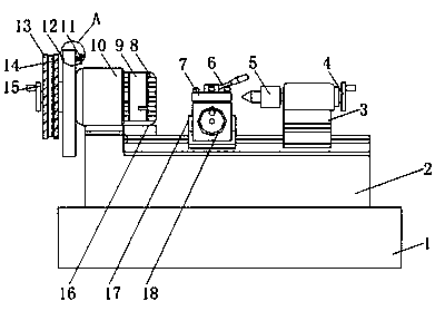
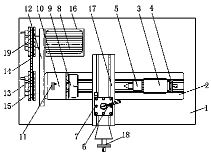
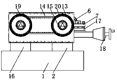
[0025] see Figure 1-4 , the present invention provides a technical solution:

[0026] A lathe with circumferential positioning and locking of the spindle, comprising a bed frame 1, a workbench 2 is fixed on the end surface of the bed frame 1, a tail needle main body box 3 is arranged on the workbench 2, and a tail needle body box 3 is fixedly installed on the right side of the tail needle main body box 3 Tail needle adjustment handle 4, the ro...


PUM


Abstract

The invention relates to the technical field of woodworking lathes, in particular to a lathe for positioning and locking a main shaft circumference. The lathe comprises a bed frame, a workbench is fixedly arranged on the end face of the bed frame, a tail needle main body box is arranged on the workbench, a tail needle adjusting handle is fixedly arranged on the right side of the tail needle main body box, a tail needle corresponds to the tail needle adjusting handle is arranged on the left side of the tail needle main body box, a cutter fixing table is arranged on the left side of the tail pinand located on the workbench, a cutter is fixedly arranged on the cutter fixing table, a pressing handle is fixedly arranged on the end face of the cutter, a cutter feeding adjusting handle is fixedly arranged below the cutter and located on the workbench, and a main case is arranged on the workbench and is located on the left side of the cutter fixing table. The application range of the machinetool is expanded, so that the uniform processing becomes accurate and easy, positions of a belt wheel and a fan belt are carved, the accessory is coordinated with the conical pin, so that multiple functions of the accessory are realized, and the structure of the machine becomes simple and compact.

Description

technical field [0001] The invention relates to the technical field of woodworking lathes, in particular to a lathe with circumferential positioning and locking of a main shaft. Background technique [0002] The woodworking lathe is a joint structure of the spindle box and the feed box. It is suitable for processing workpieces with large diameters and short lengths. High-speed steel or hard alloy tools can be used to process steel, cast iron and light alloy parts. Rough and fine turning processing such as inner hole, end face, tapered surface, grooving, cutting, etc., but the existing woodworking lathe spindle circle positioning points are few, the positioning position is not clear, and the processing fixed points are evenly divided into products, which is not convenient for stamping, and cannot expand the machine tool The scope of application makes it difficult to divide the processing accurately. [0003] To sum up, the present invention proposes a lathe with circumferent...

Claims


Application Information

Patent Timeline
IPC IPC(8): B27C7/00B23B23/00B23B19/02B23B25/06
CPCB27C7/00B23B23/00B23B25/06B23Q1/70
Inventor 殷宪勇
Owner 殷宪勇
Learn More