Optical transmission distortion compensation device, optical transmission distortion compensation method, and communication device
A technology of distortion compensation and communication device, applied in optical fiber transmission, transmission system, elimination of distortion/chromatic dispersion, etc., can solve problems such as crosstalk and removal, and achieve the effect of compensating for constellation distortion
- Summary
- Abstract
- Description
- Claims
- Application Information
AI Technical Summary
Problems solved by technology
Method used
Image

Examples
Embodiment approach 1
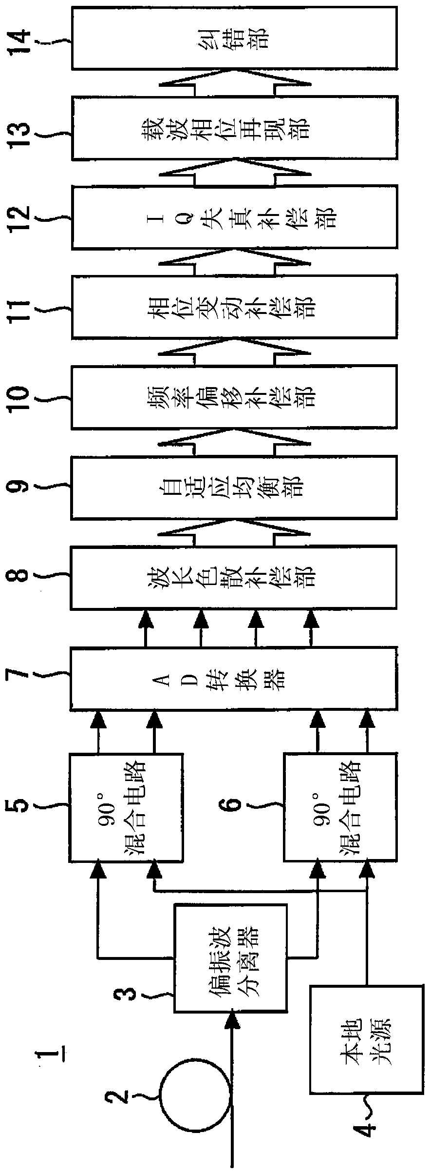
[0034] figure 1 It is a diagram showing the receiving device of the coherent optical communication device according to Embodiment 1 of the present invention. The receiving device 1 converts the optical signal received from the optical fiber 2 into an electrical signal and performs digital processing.
[0035] In the receiving device 1, first, the polarization splitter 3 splits the optical signal into two orthogonally polarized components. These optical signals and the local light of the local light source 4 are input into the 90° hybrid circuit 5, 6, and a group of output lights obtained by causing the two lights to interfere with each other in the same phase and anti-phase, and a group of output lights obtained by orthogonal (90°) can be obtained. °) and anti-orthogonal (-90°) interference, a total of 4 output lights. These output lights are respectively converted into analog signals by photodiodes (not shown). These analog signals are converted into digital signals by the...
Embodiment approach 2
[0090] Figure 7 It is a diagram showing an optical transmission distortion compensation device according to Embodiment 2 of the present invention. A skew compensation unit 18 is provided between the IQ distortion compensation unit 12 and the carrier phase reproduction unit 13 . With the addition of the skew compensating section 18, the derivation formula of the coefficient in the coefficient calculating section 17 changes. Other structures are the same as those in Embodiment 1.
[0091] Figure 8 It is a figure which shows the skew compensation part of Embodiment 2 of this invention. The skew compensation unit 18 mainly performs skew compensation for compensating the delay difference between the I component signal and the Q component signal at the time of transmission. The skew compensating section 18 has: a filter 19 that performs skew compensation of the outputs of the I component compensating section 15 and the Q component compensating section 16; The filter coefficie...
Embodiment approach 3
[0127] Figure 9 It is a diagram showing an optical transmission distortion compensation device according to Embodiment 3 of the present invention. The adaptive equalization unit 9 and the phase variation compensation unit 11 calculate filter coefficients and compensation amounts for equalization processing and compensation processing, respectively, based on the error between the known signal and the received signal. For example, as the known signal of the adaptive equalization unit 9, a long-period known pattern signal for synchronization arranged at the head position of the packet data at the level of hundreds of symbols, arranged at the level of every several tens of symbols, can be used. A short-period, known pattern signal in the data ensemble. As the known signal of the phase fluctuation compensator 11, the above-mentioned short cycle and known pattern signal can be used.
[0128]IQ distortion remains in the uncompensated received signal, but the known signal does not ...
PUM
 Abstract
Description
Claims
Application Information
 - R&D
- Intellectual Property
- Life Sciences
- Materials
- Tech Scout
- Unparalleled Data Quality
- Higher Quality Content
- 60% Fewer Hallucinations
Browse by: Latest US Patents, China's latest patents, Technical Efficacy Thesaurus, Application Domain, Technology Topic, Popular Technical Reports.
© 2025 PatSnap. All rights reserved.Legal|Privacy policy|Modern Slavery Act Transparency Statement|Sitemap|About US| Contact US: help@patsnap.com