
Rotary clamping device

A rotary clamping device and clamping technology, applied in transportation and packaging, furnace, electric charge manipulation, etc., can solve the problems of substrate quality and yield reduction, small operating range, and large restoring force of compression springs

Active Publication Date: 2021-09-14
ULVAC KOREA +1
View PDF0 Cites 0 Cited by
  • Summary
  • Abstract
  • Description
  • Claims
  • Application Information

AI Technical Summary

Problems solved by technology

The compression spring repeatedly compresses and expands to generate particles, which cause the quality and yield of the substrate to decrease
Additionally, clips that operate with compression springs only operate within the compression and extension ranges of the compression springs, so have a smaller operating range
Clamps with a small operating range cannot stably hold curved substrates
In addition, the compression spring itself has a large restoring force, so there is a risk of a strong impact on the substrate

Method used


Image

  • Rotary clamping device
  • Rotary clamping device
  • Rotary clamping device

Examples


Embodiment Construction

[0036] Embodiments are described in detail below with reference to exemplary drawings. Reference signs are added to structural elements in each drawing. It should be noted that the same reference signs are used as much as possible even if the same structural elements are shown in other drawings, and detailed descriptions of related known structures or functions are judged. This detailed description is omitted when it would obscure the invention.

[0037] In addition, terms such as first, second, A, B, (a), and (b) may be used when describing constituent elements of the embodiments. The term is only used to distinguish this structural element from other structural elements. The terms do not limit the nature, or the sequence or order, etc. of the corresponding structural elements. When some structural elements are described as being "linked", "combined" or "connected" to other structural elements, the structural elements may be directly connected or connected to other structur...


PUM


Abstract

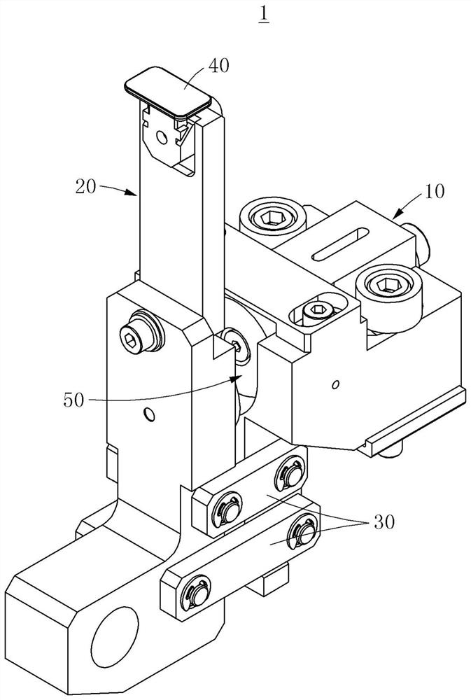
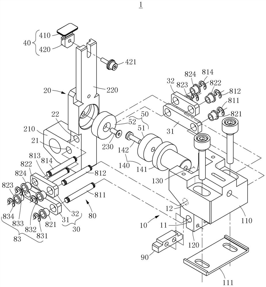
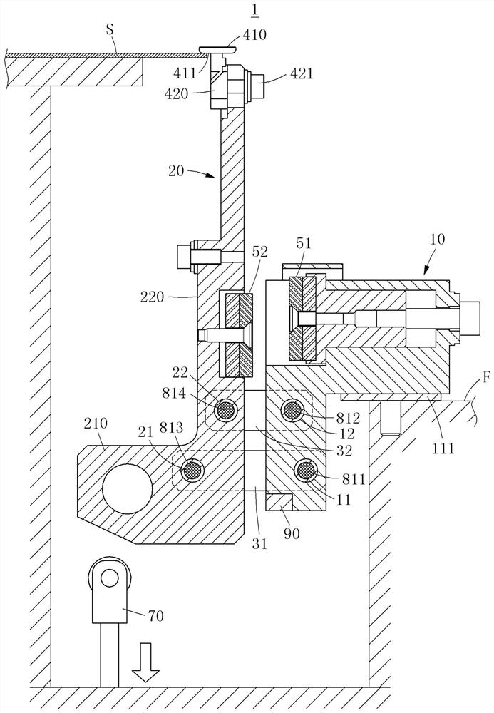
The invention relates to a rotary clamping device, which comprises: a base; a clamper capable of translational and rotational movement relative to the base; a clamping piece configured in the clamper for clamping a substrate and a link link for linking the base and the holder.

Description

technical field [0001] The invention relates to a rotary clamping device. Background technique [0002] During the preparation of the substrate, the substrate is fixed on the substrate transfer frame and transferred. Recently, in order to reduce the weight of the substrate, various methods have been implemented. For example, the substrate is carried into the sputtering chamber upright perpendicular to the ground while being fixed on the substrate transfer frame. A clamping device is used for stably fixing the substrate on the substrate transfer frame. [0003] In the existing clamping device, in order to restore the clamping piece from the dismounting position to the clamping position, a compression spring is used. The compression spring repeatedly compresses and expands to generate particles, and the particles reduce the quality and yield of the substrate. In addition, clips that operate with compression springs only operate within the compression and extension ranges of...

Claims


Application Information

Patent Timeline
Patent Type & Authority Patents(China)
IPC IPC(8): B65G49/06H01L21/677H01L21/687
CPCB65G49/06H01L21/677H01L21/687B65G49/061B65G2201/022H01L21/67739H01L21/68707
Inventor 赵显祐姜明锡郑之欢汤山明佐藤优
Owner ULVAC KOREA
Learn More