
A sedation device

A technology of sedation and casing, which is applied in the direction of medical equipment, tracheal intubation, and other medical equipment, and can solve the problem of reduced reflection efficiency of carbon filters

Pending Publication Date: 2019-02-05
SEDANA MEDICAL LTD
View PDF8 Cites 0 Cited by
  • Summary
  • Abstract
  • Description
  • Claims
  • Application Information

AI Technical Summary

Problems solved by technology

The reflective efficiency of the carbon filter can also be reduced, and thus will require a larger amount of sedative, which is undesirable

Method used


Image

  • A sedation device
  • A sedation device
  • A sedation device

Examples


Embodiment Construction

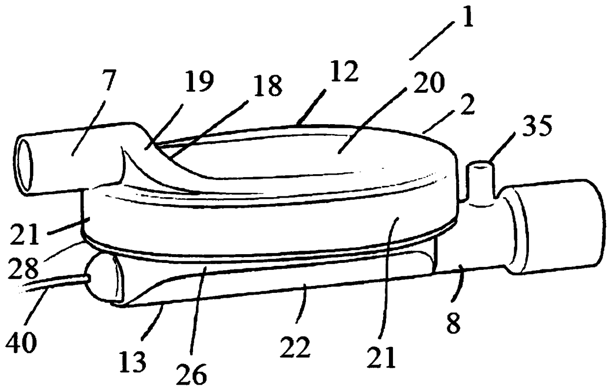
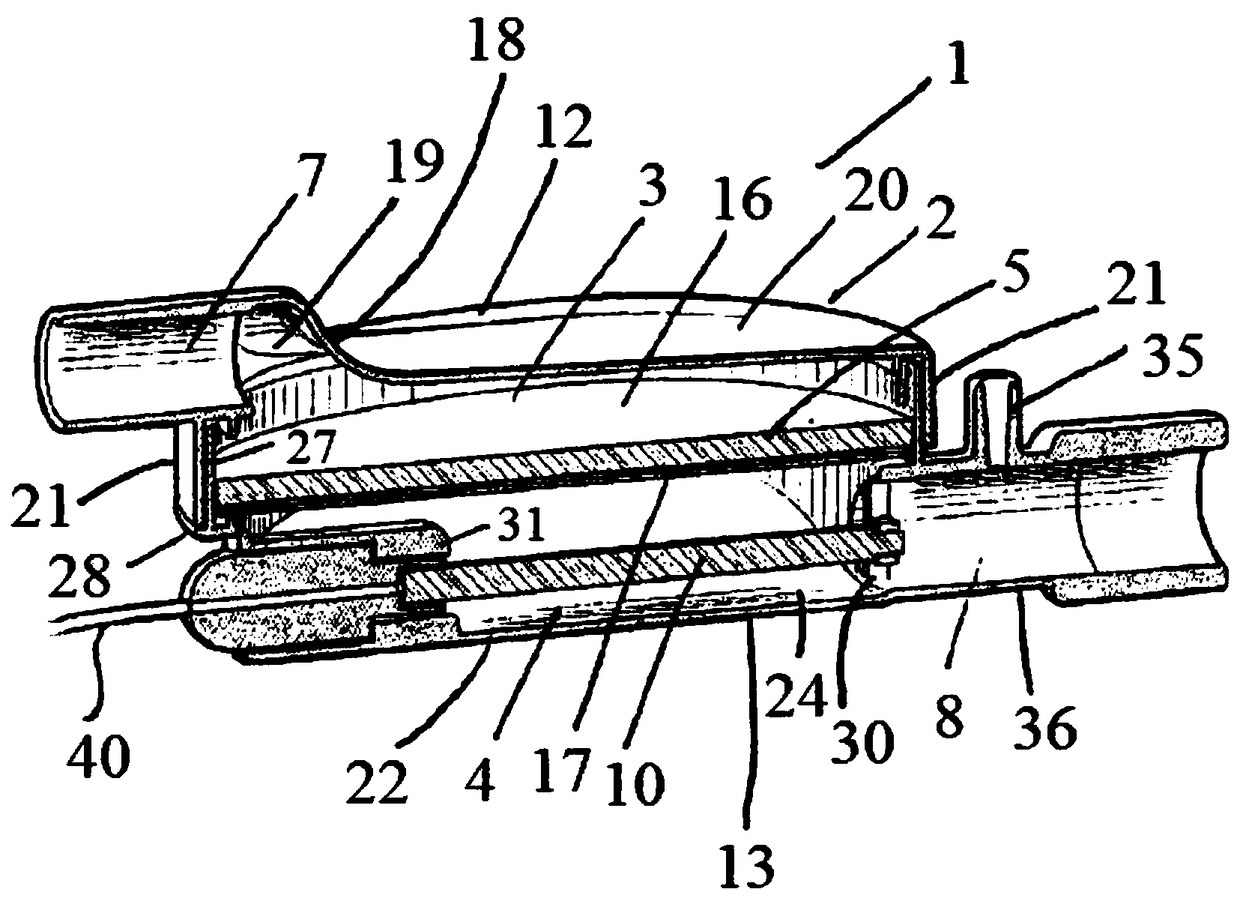
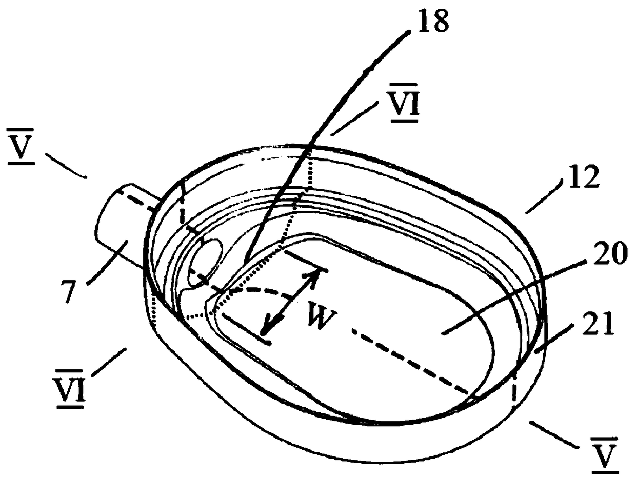
[0061] Refer to the attached drawings and initially refer to Figure 1 to Figure 9 , shows a sedation device for anesthetic agent delivery and recovery according to the present invention, said sedation device being generally indicated by reference numeral 1 . The sedation device 1 has a housing 2 in which a ventilator chamber 3 and an associated vaporizer chamber 4 are arranged, said chambers overlapping and separated by a filter 5 which Installed between said chambers 3, 4 and forming a common gas permeable partition between the chambers 3, 4. An inlet 7 is provided at one end of the ventilator chamber 3, at the top of the housing 2, for connection in use to a patient ventilator 50 ( Figure 9 ). The outlet 8 on the vaporizer chamber 4 can be connected to the patient via a breathing tube 54 . It should be noted that in this case the inlet 7 and the outlet 8 are substantially parallel and located at opposite ends of the housing 2 along its longitudinal centreline. A vapori...


PUM


Abstract

A sedation device (1) has a housing (2) divided internally into a ventilator chamber (3) and an associated evaporator chamber (4) which overlap and are separated by a filter (5) mounted between the chambers (3, 4) and forming a common gas-permeable dividing wail between the chambers (3, 4), An inlet port (7) is provided at one end of the ventilator chamber (3) at a top of the housing (2) for connection to a patient ventilator in use. An outlet port (8) on the evaporator chamber (4) can be connected via a breathing tube to a patient. An evaporator (10) is mounted within the evaporator chamber (4) for delivery of a volatile sedative into the evaporator chamber (4) during use.

Description

[0001] Introduction [0002] The present invention relates to a sedation device, and in particular, to a sedation device for sedation delivery capable of handling sedation in the form of a volatile gas. Background of the invention [0003] Volatile anesthetics are powerful agents recorded for use in general anesthesia. General anesthesia is the administration of volatile or intravenous anesthetics to induce a state of unconsciousness in the absence of pain throughout the body. Administration of volatile anesthetics usually requires anesthesia machines. The development of anesthesia machines has mainly focused on the need to minimize the consumption of expensive volatile agents in order to reduce costs and minimize the negative impact of exhaust gases on the environment. Anesthesia machines operate on the principle of a circulatory system, where they recirculate spent gas through a carbon dioxide absorber before returning it to the patient. Therefore, after the initial infus...

Claims


Application Information

Patent Timeline
IPC IPC(8): A61M16/00A61M16/18A61M16/14
CPCA61M16/147A61M16/18A61M16/107A61M2206/20A61M16/085A61M2016/1035A61M16/104A61M16/1055A61M16/1045A61M16/024A61M16/1065A61M16/01A61M16/04A61M16/142A61M16/009A61M16/101A61M2205/7509A61M16/105A61M16/106A61M2205/7518
Inventor R·法雷尔P·凯里
Owner SEDANA MEDICAL LTD
Learn More