
Automatic patrol-inspecting device for transformer substation

A substation automatic and rotating shaft technology, applied in switchgear, TV, electrical components, etc., can solve the problem of small image acquisition range, avoid shadow interference, narrow the blind area of ​​acquisition, and ensure the quality of acquisition.

Inactive Publication Date: 2019-02-05
国网新疆电力有限公司和田供电公司 +1
View PDF9 Cites 2 Cited by
  • Summary
  • Abstract
  • Description
  • Claims
  • Application Information

AI Technical Summary

Problems solved by technology

[0004] The present invention aims at the technical defects of the prior art, and provides an automatic inspection device for substations, so as to solve the technical problem that the automatic inspection device of the prior art has a small image acquisition range

Method used


Image

  • Automatic patrol-inspecting device for transformer substation
  • Automatic patrol-inspecting device for transformer substation
  • Automatic patrol-inspecting device for transformer substation

Examples


Embodiment 1

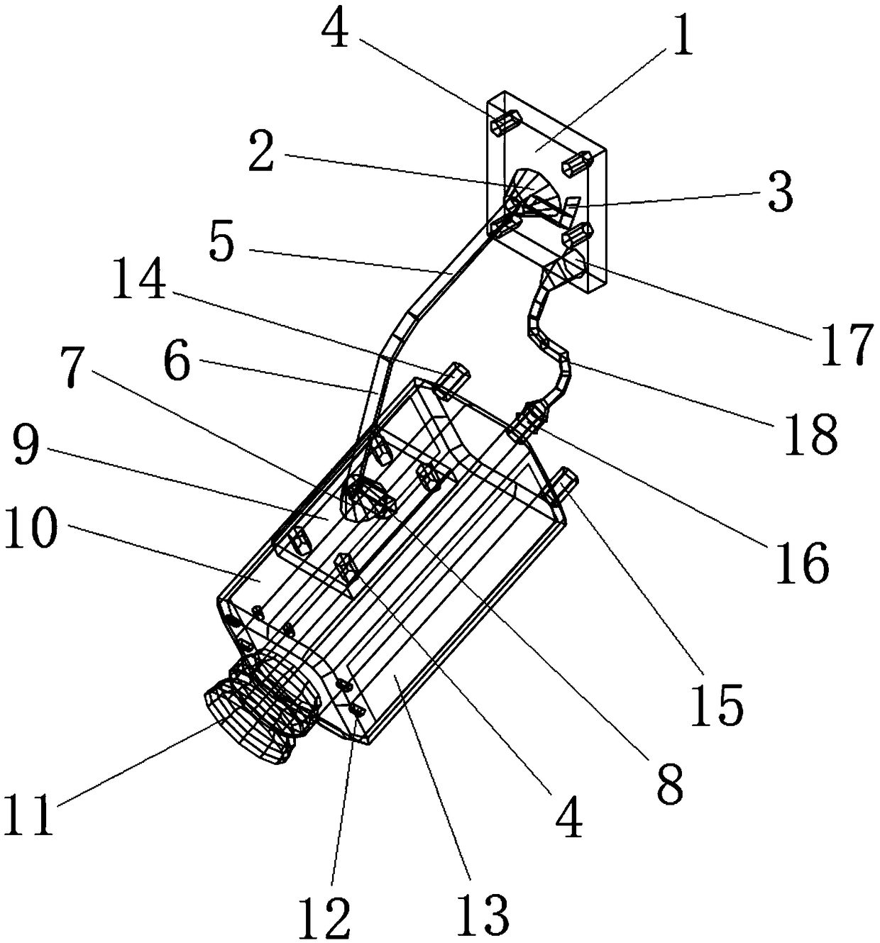
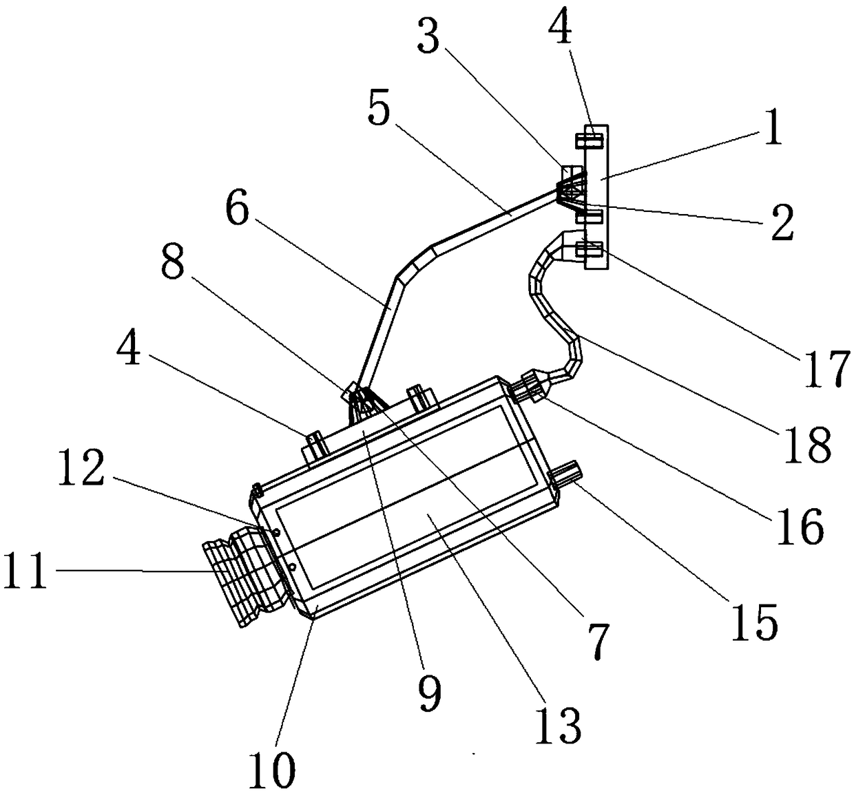
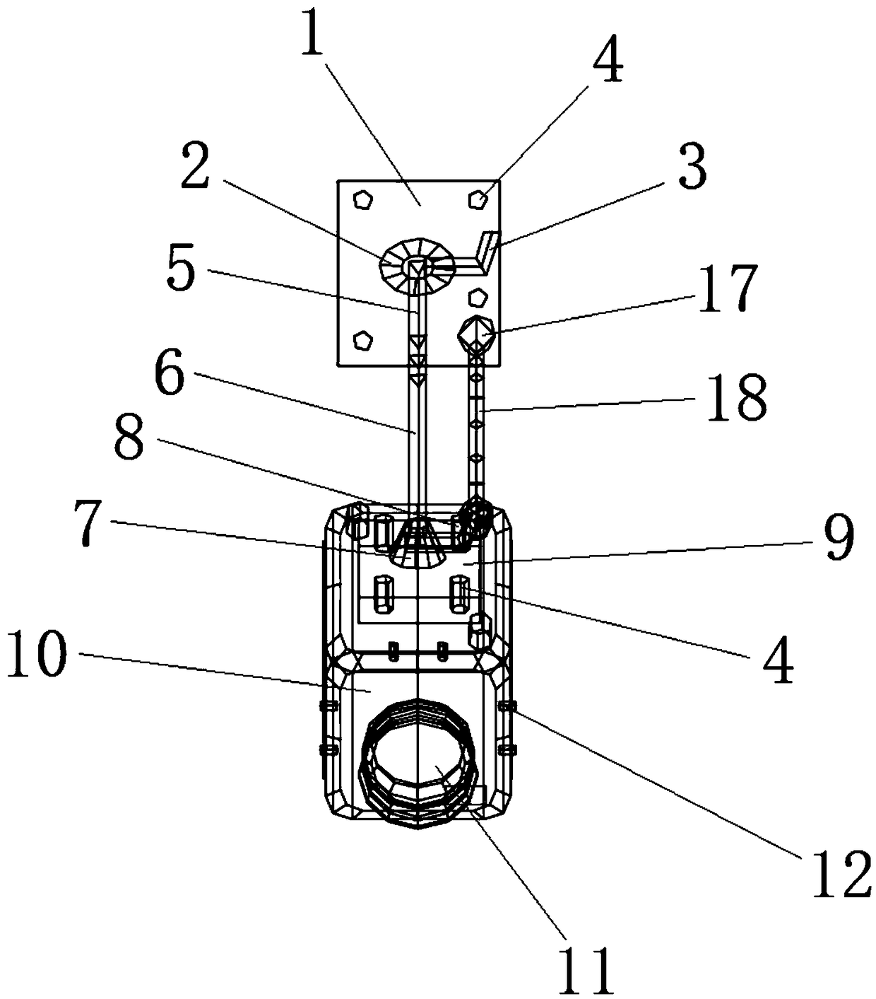
[0025] Substation automatic inspection device, such as Figure 1~3 As shown, it includes a base 1, a first rotating shaft 2, a first protruding rod 3, a bolt 4, a connecting rod 5, a bending part 6, a second rotating shaft 7, a second protruding rod 8, a connecting plate 9, a camera 10, Lens 11, supplementary light 12, panel light 13, wireless signal transmitter 14, wireless signal receiver 15, line outlet 16, threading hole 17, hose 18, wherein the first rotating shaft 2 is located on the base 1, the second A first protruding rod 3 is connected to the outer wall of a rotating shaft 2, a number of bolts 4 are connected to the base 1, a curved portion 6 is provided on the connecting rod 5, the upper end of the connecting rod 5 is connected with the first rotating shaft 2, and the curved portion 6 The lower end of the second rotating shaft 7 is connected with the second rotating shaft 7, and the second rotating shaft 7 is located on the connecting plate 9, and the outer wall of ...

Embodiment 2

[0028] Substation automatic inspection device, such as Figure 1~3 As shown, it includes a base 1, a first rotating shaft 2, a first protruding rod 3, a bolt 4, a connecting rod 5, a bending part 6, a second rotating shaft 7, a second protruding rod 8, a connecting plate 9, a camera 10, Lens 11, supplementary light 12, panel light 13, wireless signal transmitter 14, wireless signal receiver 15, line outlet 16, threading hole 17, hose 18, wherein the first rotating shaft 2 is located on the base 1, the second A first protruding rod 3 is connected to the outer wall of a rotating shaft 2, a number of bolts 4 are connected to the base 1, a curved portion 6 is provided on the connecting rod 5, the upper end of the connecting rod 5 is connected with the first rotating shaft 2, and the curved portion 6 The lower end of the second rotating shaft 7 is connected with the second rotating shaft 7, and the second rotating shaft 7 is located on the connecting plate 9, and the outer wall of ...


PUM


Abstract

The invention provides an automatic patrol-inspecting device for a transformer substation. According to the technical scheme, a movement mechanism of the device is newly designed, a bearing effect isrealized through a fixing base. A first rotating shaft is utilized to provide a rotating and moving space in a vertical plane for a connecting rod, and meanwhile, a second rotating shaft is utilized to provide a rotation space in the other plane for a camera. On the basis of a compound movement mechanism, the image acquisition range can be expanded, and the acquisition dead zone is significantly reduced. Accordingly, a plurality of light supplementing lamps are arranged on the periphery of a camera lens. The ambient light in the image acquisition process is uniformly kept by the arrangement ofthe light supplement lamps, and is basically not influenced by the brightness degree of the external environment, so that a foundation for lateral contrast analysis of image information is laid. In addition, a bundling arrangement mode of the light supplement lamps effectively avoids the shadow interference, thereby guaranteeing the acquisition quality.

Description

technical field [0001] The invention relates to the technical field of substation inspection equipment, in particular to an automatic inspection device for a substation. Background technique [0002] Substation inspection work is an important part of substation operation management. It is an essential basic work to check the operation status of equipment, master the operation rules of equipment, and ensure safe operation. By improving the quality of equipment inspection, it can improve the operation and management level of substations and ensure the safe operation of substation equipment. Traditional manual inspections use paper-based standard inspection workbooks, and inspection personnel manually fill in the inspection results. After the inspection is completed, the inspection record book will be summarized to the power grid center for filing, and necessary maintenance measures will be taken according to the fault records. [0003] Due to cost and technical problems, tra...

Claims


Application Information

Patent Timeline
Patent Type & Authority Applications(China)
IPC IPC(8): G07C1/20H04N5/235H02B3/00
CPCH02B3/00G07C1/20H04N23/74
Inventor 牛方原徐晓明陈飞董红磊陈袁奋强冯玲张颖
Owner 国网新疆电力有限公司和田供电公司
Learn More