Thread delivery device and thread brake

A technology of a braking device and a yarn guide, applied in the field of yarn guides, can solve the problems of worsening the uniformity of the pressure of the brake belt, the interference of the pressure of the brake belt, the sensitivity of the yarn quality, etc.

Inactive Publication Date: 2002-10-23
IRO AB
View PDF4 Cites 0 Cited by
  • Summary
  • Abstract
  • Description
  • Claims
  • Application Information

AI Technical Summary

Problems solved by technology

This yarn-induced influence further worsens the uniformity of the pressure of the brake band on the unwinding edge
Although this known yarn braking device can provide a particularly desirable automatic compensation effect, that is to say when the yarn unwinding speed increases or increases and thus has caused the yarn tension to rise or

Method used


Image

  • Thread delivery device and thread brake
  • Thread delivery device and thread brake
  • Thread delivery device and thread brake

Examples


Embodiment Construction

[0044] Detailed description of the preferred embodiment

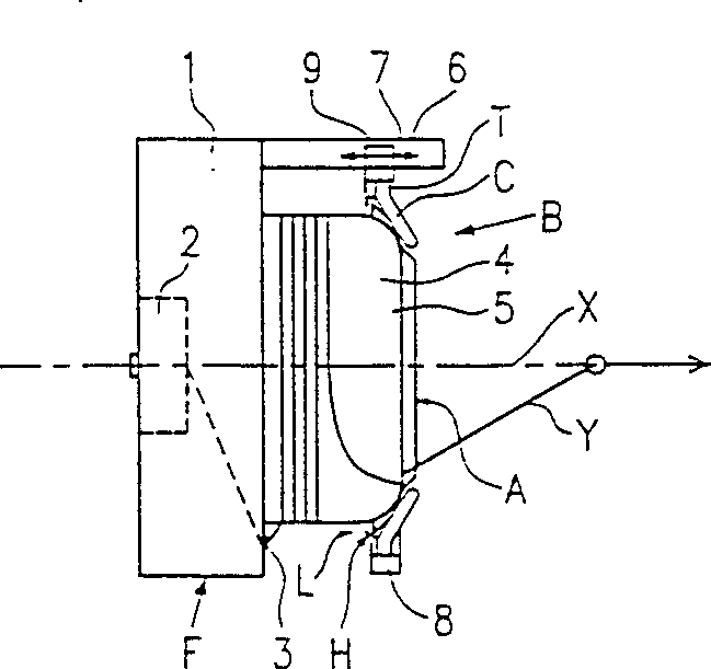
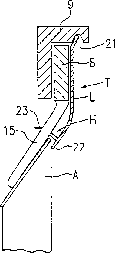
[0045] The yarn feeder F, which is equipped with a yarn braking device B, optionally forming a structural unit itself, has a drive motor 2 for the winding mechanism 3 in the housing 1 . On the housing 1 there is a drum-type yarn storage body 4 which has a circumferentially continuous circular or conical unwinding edge 5 . The yarn braking device B is fixedly supported on a support element 9 which is preferably axially adjustable in the direction of the double arrow 6 and which is mounted in the housing arm 7 . An approximately annular brake band support T is installed in the support member 9, and the brake band support T presses a circumferentially continuous brake band A generally axially (the axis X of the storage body) on the unwinding edge 5 on. The brake band is made of a wear-resistant material with a thickness between 0.01 and 1.0 mm, such as metal or metal alloy, and has the shape of a frustoconical sleeve. T...


PUM


Abstract

The invention relates to a yarn feeder (F) equipped with a yarn braking device (B), which has an axisymmetric yarn storage body (4) with a frontal unwinding edge (5), which The yarn braking zone (Z) of the yarn braking device (B) is formed towards a continuous braking band (A), which has the shape of a truncated cone sleeve and can be substantially perpendicular to the truncated cone Made of elastically deformable material for the generatrix, the above-mentioned yarn brake (B) has a fixed support (9) for the brake band holder (T), which holds the brake band (A) substantially along the axis presses elastically and elastically on the unwinding edge (5), in this yarn guide the brake band is fixed floatingly on the brake band relative to the unwinding edge (5) and relative to the brake band support (T) on the stand.

Description

technical field [0001] The invention relates to a yarn guide used in the field of textile machinery. Background technique [0002] In a yarn brake on a yarn guide known from PCT / EP94 / 00476, the brake band is glued in the small-diameter end region of a substantially conical rubber membrane which surrounds the yarn storage body And be contained in the fixed support with its large-diameter end and pull the braking band and make its inner side lean against on the unwinding edge of the yarn storage body. Such yarn braking devices are widely used in projectiles, such as projectile weft insertion looms and rapier weft insertion looms. The film is at the same time a brake band support and an elastic member, which transmits the axial pressure to the brake band and does not significantly affect the local deformation capacity of the brake band in the radial direction. Although every effort is made to form the film as uniformly as possible, the pressure exerted by the braking band on ...

Claims


Application Information

Patent Timeline
IPC IPC(8): B65H51/22D03D47/36
CPCD03D47/366B65H51/22
Inventor 库尔特·A·G·雅各布松珀·奥尔森
Owner IRO AB
Why Eureka
Try Eureka