
Array antenna

An array antenna and radiating unit technology, applied in antennas, antenna arrays, specific array feeding systems, etc., can solve the problems of lobe width convergence before and after ratio difference, unable to meet the needs of operators, and low antenna gain, etc., to achieve optimization The effect of front-to-back ratio, optimization of antenna horizontal plane pattern, and broadening of working frequency band

Inactive Publication Date: 2019-02-01
SHANGHAI HUIJUE NETWORK COMM EQUIP
View PDF9 Cites 7 Cited by
  • Summary
  • Abstract
  • Description
  • Claims
  • Application Information

AI Technical Summary

Problems solved by technology

[0003] Nowadays, with the continuous growth of mobile broadband services, inter-cell interference and user experience have become the key considerations for operators. Traditional array antennas have low gain, lobe width convergence, and front-to-back ratio difference. If they want to widen the working frequency band, they are often large in size and have a large bandwidth. There is a problem of cost, which cannot meet the needs of operators

Method used


Image

  • Array antenna
  • Array antenna
  • Array antenna

Examples


Embodiment Construction

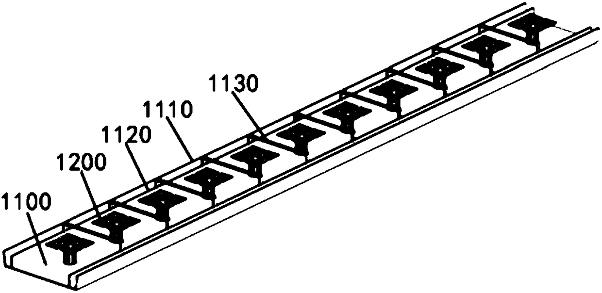
[0024] Such as figure 1 As shown, an array antenna includes a reflector 1100 and a plurality of radiation units 1200 .

[0025] The reflector 1100 is a strip-shaped metal plate, and the longer sides on both sides are folded upwards to form symmetrical folded edges 1110, and the folded angle of the folded edges 1110 is 90°-100°.

[0026] In this embodiment, the reflecting plate 1100 is stamped from sheet metal, and the folding angle of the folded edge 1110 is 98°.

[0027] The reflecting plate 1100 has two isolation plates 1120 located between the plurality of radiation units 1200 and the two folded edges 1110. The two isolation plates 1120 are symmetrically and vertically distributed on both sides of the plurality of radiation units 1200. The isolation plates 1120 can be increased Radiation current path, optimized lobe width and front-to-back ratio of the pattern.

[0028] The reflector 1100 also has a plurality of isolation strips 1130 respectively located between adjacent ...


PUM


Abstract

The invention discloses an array antenna, which comprises a reflecting plate and multiple radiation units, wherein the multiple radiation units are fixed on the reflecting plate; each radiation unit comprises a base and a radiator for forming single polarization or dual polarization; and the radiator comprises a supporting column fixed on the base and a radiation arm fixed on the supporting column. The structure of the reflecting plate is improved, in a condition of the same size, the horizontal pattern of the antenna can be optimized, radiation current paths can be increased, the lobe width and the front-to-back ratio of the antenna array can be effectively optimized, the gains of the antenna can be effectively improved, the structure of the radiation unit is optimized, the frequency coverage range is wide, a frequency band of 1710 to 2690 MHz can be effectively covered, and while the working frequency band is widened, the size is reduced and the cost is reduced.

Description

technical field [0001] The present invention relates to antennas, in particular to an array antenna. Background technique [0002] With the rapid development of wireless communication technology, 4G-LTE systems have been deployed commercially on a large scale. Operators have higher and higher requirements for communication quality. As an important part of mobile communication systems, array antennas play a vital role in communication quality. effect. [0003] Nowadays, with the continuous growth of mobile broadband services, inter-cell interference and user experience have become the key considerations for operators. Traditional array antennas have low gain, lobe width convergence, and front-to-back ratio difference. If they want to widen the working frequency band, they are often large in size and have a large bandwidth. There is a problem of cost, which cannot meet the needs of operators. Contents of the invention [0004] Based on this, an array antenna is provided ai...

Claims


Application Information

Patent Timeline
Patent Type & Authority Applications(China)
IPC IPC(8): H01Q1/12H01Q1/36H01Q1/50H01Q15/18H01Q19/10H01Q19/17H01Q21/00H01Q21/08
CPCH01Q1/12H01Q1/36H01Q1/50H01Q15/18H01Q19/106H01Q19/17H01Q21/0006H01Q21/08
Inventor 吴小芳马亮卫文志
Owner SHANGHAI HUIJUE NETWORK COMM EQUIP
Learn More